
Installation Manual

INSTALLATION ON THE VEHICLE
24
The technical materials and information contained in this document are strictly confidential and the exclusive property of Advanced Microwave Engineering s.r.l.
These materials and information are intended solely for the purpose designated and may not be used otherwise.
It is not permitted to disclose or reproduce them in whole or in part without express written permission.
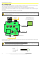
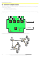
8.3.4 Connecting the HUB
Connect the sensors to BUS 2 by means of UTP cable following the indications given in the sensor connection section.
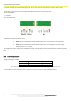
When crimping the UTP cable, follow the same sequence of colours on each cable end.
Connect the HUB to the CPU by means of the BUS 1 connector using a cable belonging to CAT. 5e or higher.
Connect the power supply to the EXT POWER connector using an AWG 18/0.75 mm
2
bipolar cable or a cable with a higher
cross section.
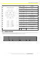
Insert the ferrite, 74271132S type or equivalent, in the power cable
The device is powered in direct current with a voltage between 12/24 V.
The power supply to the device must be limited to a maximum of 4A/32V. Use a fuse directly fitted on the
positive-pole conductor.
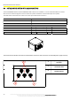
Connect the antenna supplied together with the system. Observe the polarity. The braiding should be on GND and the
central conductor on 'ANT'.
The antenna support must be kept isolated from the
chassis
of the vehicle
.
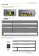
Observe the measurements shown in the figure to strip the RG58 cable of the antenna. Stripping the cable too
much may impair the correct RF performance of the system.
ANT RF
OUTPUT
1
EXT PWR
BUS1
BUS2 BUS2 BUS2
BUS2 TX
BUS2 RX
ADR_HUB
SW1
RL2
RL1
+3.3V
GND
ANT
GND
NC
C
NO
NC
C
NO
GND
+12/24VDC
AWG18/0.75mm2
SENSOR INPUT
CPU INPUT
CONNECTOR
EXTERNAL RF
ANTENNA
POWER SUPPLY CONNECTOR
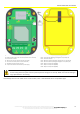
It is recommended to keep the
coaxial antenna cable away from
the area highlighted by the square