
Installation Manual

INSTALLATION ON THE VEHICLE
23
The technical materials and information contained in this document are strictly confidential and the exclusive property of Advanced Microwave Engineering s.r.l.
These materials and information are intended solely for the purpose designated and may not be used otherwise.
It is not permitted to disclose or reproduce them in whole or in part without express written permission.
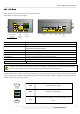
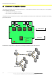
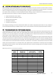
A1 – MW transmission antenna uFL connector (antenna already connected) LED1 – vehicle-vehicle reception signal (flashing)
A2 – MW reception antenna uFL connector (antenna to be connected)
LED2 – LF transmission (flashing) and diagnosis error (steady off)
A3 – RF test uFL connector LED3 – ON status indicator
J9 – RF antenna connector (antenna already connected) LED4 – MW status indicator (flashing) and diagnosis error (steady off)
J3 – LF antenna connector (antenna to be connected) LED5 – RF status indicator (flashing) and diagnosis error (steady off)
J1 – data BUS and power supply connector LED6 – Relay 1 active/inactive (ON/OFF)
J8 – relay terminal board and stand-alone power supply LED7 – Relay 2 active/inactive (ON/OFF)
LED8 – Relay 3 active/inactive (ON/OFF)
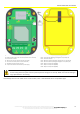
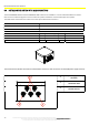
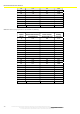
While the sensor is
closing back, make sure that the A2 and J3 connectors are connected; prevent the cables
from finishing above the patch antenna (central panel of the figure on the left). Make sure that the sealing O-
ring is placed back in its housing.
Immediately after the UTP cable comes out of the box, insert a 74271132S ferrite or an equivalent type.