
Installation Manual
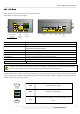

INSTALLATION ON THE VEHICLE
21
The technical materials and information contained in this document are strictly confidential and the exclusive property of Advanced Microwave Engineering s.r.l.
These materials and information are intended solely for the purpose designated and may not be used otherwise.
It is not permitted to disclose or reproduce them in whole or in part without express written permission.
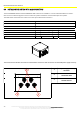
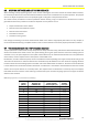
8.3.2 CPU Wiring
All the devices of the system must be connected to the CPU.
The available connectors are as follows:
Power supply
/turning-on
HUB
Sensors
(RJ45)
Display
connector
Relay I/O
GPS
USB LAN
POE
RS 232
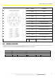
Power supply/turning
-
on
To power the CPU and some of the accessories that can be installed
RS 232
To connect the BADGE module
SENSORS
To connect the HUB and other accessories of the system (FILTER SENS, INDOOR
SPEED SENSOR, SHOCK SENSOR)
Display Connector
To connect the display, the touchscreen and the audio
Relay
Clean contacts to connect to the vehicle
I/O
I/O signals for managing additional functions
GPS Antenna
To connect the antenna of the GPS module (if any)
USB
To connect periph
erals devices for downloading data/updates/maintenance
POE LAN
To connect the Wi
-
Fi Module and the cellular router
Caution: this is a POE 10/100 LAN port, mode B, "DC on spares" and therefore, it must not be used with devices
that are not suitable for this type of connection (e.g., notebooks, Ethernet switch, etc.)
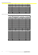
The CPU is powered at 12-24V, and it needs a specific +VQ line (under key). The CPU remains turned on even when the
vehicle is off in low consumption mode (stand-by). Activation takes place when voltage is supplied to the VQ terminal. This
enables a quick turning-on of the system.
+VIN 12/24 VDC power supply
GND Negative supply voltage
+VQ
12/24 VDC positive voltage of the turning-on signal of the
board
RELA Y1 RELA Y2
NO
COM
NC
NO
COM
NC
I/O
C1
C2
GND
GND
O1
O2
GPS
USB1
USB2
LAN
POE
!
A
B
C
D
E
F
GHJ H
K
L
M
N
P R
S T
U
V
W
X
Y
Z
a
b
c
PWR-IN
+VIN
GND
+VQ
RS232
TX
GND
RX
SENSORS DISPLAY
TX
GND
RX
+V
IN
GND
+V
Q
PWR IN
RS232