
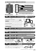
Installation guide

Grey
Grey
Red
Green
Blue
Black
Purple
7.5A
7.5A
15A
15A
15A
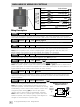
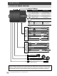
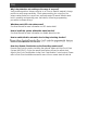
Main Harness
8-Pin 18 AWG
Parking Light
Parking Light
Battery +12V
Lock
Unlock
Ground
Horn Control
+
-
+
+
-
-
-
JP3
JP4
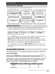
Brown
Trunk Release
-
Brown
OUTPUT
500mA
Trunk Release
Connect to the negative side of the trunk release trigger. This output will provide 1 second pulse
when UNLOCK button is pressed for 2 seconds. (This function is disabled when ACC input is ON)
Grey
OUTPUT
7.5A
Parking Light x2
Connect to the positive side of parking lights or the hazard light switch for same effect.
Red
OUTPUT
15A
Battery +12V
Connect to a +12v source. Ensure that the OEM source wire used is fused for more than 15A.
Note: When no suitable +12V source available (where current capacity is less than 15A) use
Green
OUTPUT
15A
Lock
Connect this output directly to the negative-triggered door lock signal wire.
Blue
OUTPUT
15A
Unlock
Connect this output directly to a negative-triggered door unlock signal wire.
Note: This system outputs a single unlock pulse by default. Jumper (JP3) provides a double unlock
pulses output option for vehicles that require a two consecutive unlock-pulse to unlock/disarm or to
bypass the Driver Door Priority Unlock function to unlock all doors.
Black
OUTPUT
15A
Ground
Connected to bare, unpainted metal on chassis. It is recommended to use a factory ground bolt
rather than a self-tapping screw. Screws tend to get loose or rusted over time and lead to erratic
electrical problems.
Purple
OUTPUT
500mA
Horn Control
Connect to the negative side of horn for audio notification.
Note: This system is programmed for muted Lock/Unlock
operation by default. If audio notification is desired for arming
and disarming; connect Horn Control output to a siren* and
change the jumper setting (JP4) to Siren Output option
(Refer to Horn or Siren Mode in Programmable Features).
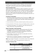
Note: If siren control is a positive type or require more than
500mA to operate; add a relay according to the diagram on
the right to convert output to a positive type.
4
© Copyright Advanced Keys Inc. 2011. All Rights Reserved.
MAIN HARNESS WIRING DESCRIPTIONS
Wiring Description:
JP1 JP 2 JP3 JP4
̶
Negative (-) to Positive (+)
Output Conversion
Horn
Control
Output
(-)
+12V
NO
COM
NC
87
87A
30
85
86
*Siren not included
+
+
JP4
JP3
̶
̶
̶
̶