AK-PSB06 REV: A06-13-0901 A D VA N C E D K E Y S Push-Start Ignition System INSTALLATION GUIDE Product Features: • • • • • • • • • * Push-Start Ignition Operation OEM Toyota Push-Start Button One-Touch Engine Tach Ignition Backup Ignition Relays Diesel Wait-to-Start Input Immobilizer Bypass Enable Trigger Remote Start Function with AK-103 Compatible with Aftermarket Alarms Compatible with OEM Vehicle Setup www.advancedkeys.com support@advancedkeys.com © Copyright Advanced Keys Inc. 2013.
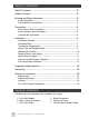
TABLE OF CONTENTS Table Of Contents ....................................................................................... 2 Product Contents ........................................................................................ 2 Warning and Safety Information ................................................................. 3 Safety Precautions ................................................................................... 3 Pre-installation Considerations ..........................................
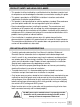
WARNING AND SAFETY INFORMATION PRODUCT SAFETY AND LEGAL DISCLAIMER • This product shall be installed by a certified technician therefore a certain level of competence and knowledge are therefore assumed when reading this guide. • This guide is provided as a GENERAL installation instructions and vehicle subjected to installation maybe different. • This product is designed based on vehicle regulatory standard. Please observe your local public road traffic law and regulations prior to installation.
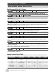
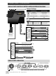
CONNECTIONS - HARNESS MAIN HARNESS WIRING DESCRIPTIONS --Main Harness 8-Pin 14-16 Gauge Purple OUTPUT - 500mA + 30A Negative START OPTIONAL Connect this output to a data bypass module or vehicle’s Negative(-) triggered Starter input. This output is rated for 500mA. DO NOT use this output to drive Starter Motor’s Negative(-) side directly. White OUTPUT Positive START Connect this output to vehicle’s Starter input at the ignition switch.
ACCESSORY HARNESS WIRING DESCRIPTIONS Accessory Harness 10-Pin 22 Gauge Orange OUTPUT + 250mA Bypass Module Control OPTIONAL This wire provides a constant 250mA positive output while the system is in ACC, ON and START states. The output can be used to activate external relays, bypass device and bypass (+)type keysense input etc. Red INPUT + Backup Relay +12v OPTIONAL Pre-connected to the external backup relays. This output provides constant +12v for ON 1 and ON 2 backup relays.
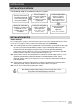
CONNECTIONS - CONTROLLER PUSH-START IGNITION CONTROL MODULE WIRING DIAGRAM JP1 JP2 JP3 Jumper Settings: JP4 Default Settings Optional Settings JP1 Tach Ignition Tachless Ignition JP2 Smart Key Enable Ground Enable JP3 Remote Start Enable* Remote Start Disable* JP4 N/A N/A *Remote start function only available with Advanced Keys’ Smart Key module.
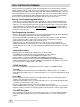
INSTALLATION INSTALLATION OVERVIEW Use following steps as a guide to install this system: Review product manual and vehicle’s electrical service manual. Prepare vehicle for installation. Mount push-start button and bypass steering lock if applicable. Secure controller and close-up installation. Review Installation Notes and set (internal) jumper settings according to customer requirements. Install Immobilizer/Data Bypass if required. Connect Main and Accessory Harness to vehicle/bypass device.
TACH IGNITION PROGRAMMING Follow steps below to program Tach signal for Tach Ignition Mode. This function allows automatic START (crank) the engine by single tap the push-start button. Prior to programming, check to ensure Tach input and ignition outputs (ACC, ON and START) with applicable immobilizer bypass device are connected/programmed. To enter Tach Program Mode, make sure vehicle ignition if OFF and system is enabled with push-start button’s Status LED light is Amber.
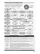
IGNITION TEST AND TROUBLESHOOTING Use the flow diagram/table below to verify Push-Start ignition function and use it for troubleshoot ignition issues.
REMOTE START FUNCTION (OPTIONAL) A built-in Remote Start function is available when system is connected with an Advanced Keys Smart Key System. To enable remote start function the following conditions are required: • Internal Jumpers JP1, JP2 and JP3 are set at their default position. • Purple “Push-Start Enable” input is connected to AK-104 Smart Key System or newer. See www.advancedkeys.com for more information. • System successfully programmed for Tach Ignition and has passed Ignition Testing.
STEERING COLUMN LOCK BYPASS To achieve complete keyless ignition, OEM steering column lock anti-theft feature needs to be bypassed. We do not recommend disabling the steering column lock permanently by removing the cylinder lock, however the “Shaved-Key” method is an easy and completely reversible way to bypass this function: 2 3 4 3 5 1. Have a local locksmith duplicated a factory key. Note: Do not modify factory keys, it is not required. Duplicate the key blade only not the RF chip inside. 2.
KEYSENSE FUNCTION BYPASS (OPTIONAL) Most vehicle has an mechanical key trigger that gets activated when a key is inserted into the key cylinder. Keysense input usually activates certain pre-programmed reactions such as (not limited to) door-chime, turn ON dome light, headlight and instrument cluster illumination, disabling the OEM remote/key's ability to lock/unlock doors and release trunk etc.
FAQ How does Push-Start Ignition work and how do I know it is working normally? Refer to “Push-Start Operation Overview” on page 6 for Push-Start Ignition Sequence and follow the “IGNITION TEST AND TROUBLESHOOTING” diagram on page 9 to verify system operation. Why is the Push-Start button dead / not working? Check system's input power and make sure there is a proper signal applied to "Push-Start Enable" input depending on Jumper 2 (JP2) setting. Amber Status LED indicates system is Ready.
FAQ My engine is running how do I turn it off? 1. If the Status LED is flashing GREEN, see question “Why is my push button turn flashing green after started?” 2. If the Status LED is OFF and Backlight is ON, then system is in RUN mode. To exit RUN mode, apply the brake and press and hold the button for 2+ sec to switch back to READY or OFF mode.
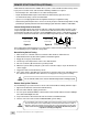
• Connecting the wire harnesses and power ON the controller, check and confirm system operations (Refer to Ignition Test and Troubleshooting) verify functions of the vehicle are in working order. • Make sure all wiring connection are insulated properly. Place and secure control units to locations inside trim panels and bundle all lose wiring. Put back all trim panels • When mounting the controller unit in the vehicle, consider the location carefully.