QSP-660 Owner’s Manual and Operating Instructions Instructions for basic operation and installation P/N 000-0865-002 c Advanced Technology Video, Inc. 14842 NE 95th Street ž Redmond, Washington 98052 Phone 888/288-7644žž425/885-7000žžFax 425/881-7014 Customer Service: sales@atvideo.com Technical Service: tech@atvideo.com Home Page: http://www.atvideo.
Table of Contents Introduction .................................................................................................................................................................... 3 Operational Features Description .................................................................................................................................. 3 Live Camera Displays .................................................................................................
Advanced Technology Video, Inc. INTRODUCTION Thank you for purchasing Advanced Technology Video’s QSP-660 four camera Real Time Quad. This instruction manual describes the powerful features of this product for basic and advanced operation. It also covers the installation steps that will allow quick and easy integration into your security system. The following section provides an overview of the operational features of the QSP-660.
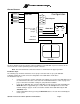
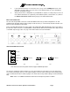
Advanced Technology Video, Inc. GETTING STARTED Camera Configuration QSP-660 Camera Alarm Inputs Camera Camera VCR Optional for VCR recording changes (Optional) Alarm Out 10K OUT IN VCR-IN VCR OUT VIDEO OUT Monitor The above diagram shows the typical 4-camera installation for the QSP-660. Up to four cameras can be connected to the real time quad using the back panel connectors. Note: The VCR and monitor connections must be as shown above for proper operation.
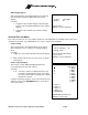
Advanced Technology Video, Inc. 4. If your VCR has internal on-screen menus for its set up, use the VCR Bypass feature of the QSP-660 to view the VCR’s on-screen menus on the display monitor. See the “VCR Bypass Function” description on page 3. 5. At this point, the basic configuration of your QSP-660 is complete. You may now proceed to set more advanced functions as required for your installation (alarms, camera labels, etc.
Advanced Technology Video, Inc. OPERATION Your QSP-660 has seven mode control buttons and four numbered camera buttons which allow easy access to all modes of operation. The seven mode buttons on the left are used to control monitor display operations and VCR playback. An LED below each button will light when the unit is in the mode corresponding to that button. Note: Live camera display modes will affect recording. Following is a summary of each button’s function and the QSP-660 operating modes.
Advanced Technology Video, Inc. REMOTE CONTROL OPERATION The IR remote control provided with your QSP-660 has a limited set of buttons. Operation with the remote control is slightly different than the front panel. The remote control has a single CAMERA button for selecting cameras and successive button presses will rotate through the available cameras. Sequencing is initiated by pressing and holding the remote control’s FREEZE button for approximately 3 seconds.
Advanced Technology Video, Inc. SET UP MENUS The QSP-660 set up is accomplished through its on-screen menus. To enter the menu system, push and hold the DISPLAY button for approximately 3 seconds. The display will then show the top-level menu. Selection of any menu item is done with the camera buttons. Selecting DISPLAY will exit the present menu level. Main Menu Selecting: 1. Enters Set Time/Date menu to program the internal clock and select time and date display options. 2.
Advanced Technology Video, Inc. Other Display Options This menu determines the display behavior of the date and time information for both the VCR and monitor camera displays. Selecting: 1. Toggles the time and date display location through any one of the four display quadrants for live camera displays. Other Display Options 1: Location 2: Display Lower Right On Camera: Select DISPLAY: Accept and Return 2. Toggles the time and date for the monitor display On/Off.
Advanced Technology Video, Inc. Sequence Set Up A unique feature of the QSP-660 is the option to customize the display sequence format to suit your application. You can program a specific selection of cameras for sequencing. Selecting: Display Sequence Set Up 1. Enters edit mode for hold (dwell) time. While editing: 1-4 5-6 DISPLAY Used to enter digits 1 through 4 VCR + 1-2 Completes the entry if less than three digits and returns to the previous value if no digits are entered. 2.
Advanced Technology Video, Inc. Sequencing Format Screens Full Camera Display Sequence 1: Cameras: 1 2 3 4 Quad Display Sequence 1: Upper Left: 2: Upper Right: 3: Lower Left: 4: Lower Right: 1... .2.. ..3. ...
Advanced Technology Video, Inc. Alarm Set Up Alarm Set Up Selecting: 1. Enters individual cameras for External Alarms menu. 2. Enters individual camera Video Loss Alarms. 3. Enters Set Alarm Enable Schedule menu. 4. Enters Enable Scheduled Alarms menu. 5. (Press VCR+1) Enters Alarm Control Options menu. 6. (Press VCR+2) Enters Alarm Log menu. 7. (Press VCR+3) Toggles Serial Alarm Output between On and Off. (The factory default is “Off”).
Advanced Technology Video, Inc. Alarm Scheduling The QSP-660 contains a very flexible and advanced alarming system designed to provide an optimum solution for any installation. Along with the ability to enable various types of alarm inputs, a built in 7-day timer may also be used to individually enable and disable each alarm. The following menus are used to set the timer and select which alarms the timer will control.
Advanced Technology Video, Inc. Alarm Control Options Selecting: 1. Enters the Set Alarm Hold Times menu. 2. Enters the Set Alarm Activation Type menu. 3. Toggles the External Control Input between Picture Freeze and alarm Master Enable. (The factory default is “Picture Freeze”.) 4. Toggles the alarm Master Enable Input Type between Logic Low and Logic High. (The factory default is “Logic Low) Alarm Control Options 1: Set Alarm Hold Times . . . 2: Set Alarm Activation Type . . .
Advanced Technology Video, Inc. Alarm Activation Type Selecting: 1-4 Set Alarm Activation Type Toggles individual camera alarm types between Contact Closure, Contact Open, Logic Low, or Logic High, triggering the alarm. 1: Contact Closure 2: Contact Closure 3: Contact Closure 4: Contact Closure In many applications the switch contact connection is between the alarm input pin and the chassis or signal ground.
Advanced Technology Video, Inc. Other Options The Other Options menu provides access to the advanced QSP-660 systems options. Selecting: 1. Toggles the IR remote control code setting between Code 1, Code 2, and remote Off. (See “Programming your ATV QSP-660 Remote Control” on page 17.) Other Options 1: Remote Control: 2: Security Set Up . . .
Advanced Technology Video, Inc. HAND HELD IR REMOTE CONTROL The hand held remote control allows easy remote operation of your QSP-660 by duplicating the front panel buttons as shown in the diagram. One major difference between front panel and remote operation is that the individual camera buttons have been reduced to a single button. In this case, the first press of the camera button will cause the QSP-660 to display camera 1.
Advanced Technology Video, Inc. ALARM INTERCONNECTION ON THE QSP-660 1K Ohm The alarm connector on the back panel allows input of four external control signals to affect the behavior of the real time quad under alarm conditions. Alarm inputs are provided for each camera. A picture freeze input is also provided to allow the picture to be frozen. These inputs are normally generated by a switch located at a door, window, or other point in the installation where a camera is monitoring activity.
In some installations, the alarm output is used to activate or deactivate high voltage and/or high current circuitry (110 VAC lights, siren, etc.) which cannot be controlled directly by the QSP-660. The easiest method to address the above cases is to use a relay, which has the number and rating on its contacts sufficient for the alarm output. Shown below are two methods to control a high current or high voltage device using a relay with a single, normally open contact.
RS-232 REMOTE CONTROL INTERFACE The QSP-660 has a built in RS-232 serial interface that supports remote control of the QSP-660 through simple ASCII commands. These commands provide access to the front panel button operations just as the IR Remote Control does. The QSP-660 serial interface is fixed at 2400 baud, 8 bits, 1 stop bit, and no parity.
EQUIPMENT REQUIREMENTS The QSP-660 is designed to be compatible with all EIA and CCIR compatible equipment. The QSP-660 will accept 2:1 interlace cameras in either a line-locked or free running (internal reference) modes. The use of random interlace camera is not recommended unless the line lock is turned off. SPECIFICATIONS Physical Dimensions...........................................................11-5/16 w X 9 d X 2-3/8 h (288 mm X 229 mm X 61 mm) Weight .................
WARRANTY INFORMATION Thank you for purchasing this Advanced Technology Video, Inc., hereinafter ATV, product. We have manufactured this product in accordance with high quality standards and when used in the manner intended, it has a limited warranty against defects in material and workmanship for a period of five (5) years from the date of shipment from ATV.