
Installation Guide

2 4640 TRUEMAN BLVD. HILLIARD, OH 43026 (800) 821-6710 www.ads-pipe.com
A
IG102 © ADS 2008
Trench Construction
• Trench or ditch should be just wide enough to place and compact backfill
around the entire pipe. Increasing the trench width increases the soil load on
the pipe. Where trench walls are stable or supported, provide a width
sufficient, but no greater than necessary, to ensure working room to properly
and safely place and compact embedment materials. The space between the
pipe and trench wall must be enough for the compaction equipment used in the
pipe zone. Minimum width shall be not less than the greater of either the pipe
outside diameter plus 16 in. (400 mm) or the pipe outside diameter times 1.25,
plus 12 in. (300 mm).
• For parallel pipe installations, allow 12” (300mm) between the pipes.
• As with any pipe, groundwater or seasonal high water tables may
impede installation. De-watering is necessary for a safe, and effective
installation.
• Trench or ditch bottoms containing bedrock, soft muck or refuse, or
other material unable to provide long-term pipe support are
unacceptable. Unsatisfactory backfill shall be removed as specified by
the design engineer.
• Unless otherwise specified or instructed by a soils specialist, rock or
unyielding material shall be removed to 1-foot (300mm) below grade
and 6” (150mm) on either side of pipe and replaced with a suitable
material as directed by the design engineer.
• Unless otherwise specified or instructed by a soils specialist, soft areas shall be excavated approximately 2 feet
(600mm) below grade and three times pipe width and replaced with a suitable material as directed by the design
engineer.
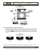
• For a flat bottom trench, bedding must be used for support as in Figure 1. Bedding shall be loosely placed
directly under the pipe while the remainder shall be compacted in accordance with Table 1. Shaped trench
bottoms may be used in accordance with ASTM F 449, see figure 2.
• If soft area remains after excavation or if native soil can migrate into backfill, use an approved synthetic fabric
(geotextile) to separate native soil from backfill as recommended by the design engineer.
Backfill Envelope Construction
• Place and compact backfill in layers to the meet the requirements of Table 1.
• Pipes laid in parallel installations require the same backfill support.
• Place and compact initial backfill in layers around pipe and at least 6” (150mm) above the crown as shown in
Figure 1.
• Avoid impacting pipe with compaction equipment. Inspect if there is a question regarding damage.
• The final minimum cover shall be 1’ (300mm) for 3”-24” (75-600mm) pipe, measured from the crown of the pipe to
final grade. For paved surface applications, flexible (asphalt) pavement thickness should not be included in the
minimum cover as shown in Figure 1.
• If sufficient cover is not provided, mound and compact material over pipe to provide minimum cover needed for
load during construction. Note: Construction traffic is heavier than typical roadway vehicles and will require a
greater amount of minimum cover.