
User Manual
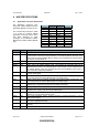
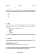
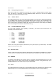
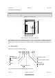
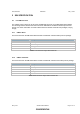
Table Of Contents
- ABBREVIATIONS
- INTRODUCTION
- PRODUCT DESCRIPTION
- HW SPECIFICATIONS
- SW SPECIFICATION
- REFERENCES

DSH, Datasheet 903501205 May 1, 2003
Zensys A/S ZM1220 Z-Wave Module Page 13 of 15
CONFIDENTIAL
4.13 Physical Specification
Physical Description
Dimension (H x W x D) 7 mm x 50 mm x 40.5 mm
Mounting holes Two holes.
Table 8 Physical Specifications
31.0mm
25.0mm
Button
2.0mm
H2
Pin 19
29.0mm
J1
Pin 20
12.0mm
35.0mm
50.0mm
PCB Antenna
Holes
40.5mm
Pin 1
Figure 2 ZM1220 Z-Wave Module PCB outline
The Application Connector is a standard 2mm pitch 2x10 pin-row. The pad hole is a Ø0.9mm plated hole.
When implementing the ZM1220 Z-Wave Module in a product together with an Application Module any
metallic objects must be min. 10mm from the PCB antenna. For detailed design recommendations see
[7].
4.14 Module Naming
Explanation of the Z-Wave Module naming.
US Z M 12 20 – R E
Z-Wave
M
odule
ZW01
02 Single Chip
E
EPROM mounted
R
eal Time Crystal mounted
Module Size:
20
= 20cm
2
PCB
06 = 6cm
2
PCB
Frequency:
US
= 908.42MHz
EU
= 868.42MHz
For more information on the ZM1206 Z-Wave Module see [2].