
User's Manual

ACR1281U
Advanced Card Systems Ltd. Page 56 of 81
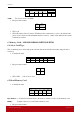
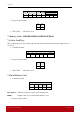
PROT 1 PROT 2 PROT3 PROT 4 SW1 SW2
• PROT y Bytes containing the protection bits from protection memory
• SW1, SW2 = 90 00 if no error
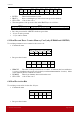
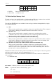
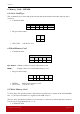
• The arrangement of the protection bits in the PROT bytes is as follows:
•
PROT 1 PROT 2 …
P8 P7 P6 P5 P4 P3 P2 P1 P16 P15 P14 P13 P12 P11 P10 P9 .. .. .. .. .. .. P18 P17
• Px is the protection bit of BYTE x in the response data
• ‘0’ byte is write protected
• ‘1’ byte can be written
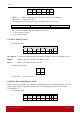
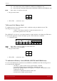
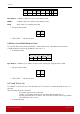
6.5 Write Memory Card
• Command format
Pseudo-APDU
CLA INS P1 Byte
Address
MEM_L Byte 1 .... .... Byte N
FF
H
D0
H
00
H
Byte Address = A7A6A5A4 A3A2A1A0 b is the memory address location of the memory card.
MEM_L Length of data to be written to the memory card.
Byte x
Data to be written to the memory card.
• Response data format
SW1 SW2
• SW1, SW2 = 90 00 if no error
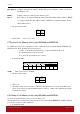
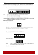
6.6 Write Protection Memory Card
Each of the bytes specified in the command is internally in the card compared with the byte stored
at the specified address and if the data match, the corresponding protection bit is irreversibly
programmed to ‘0’.
• Command format
Pseudo-APDU
CLA INS P1 Byte
Address
MEM_L Byte 1 .... .... Byte N
FF
H
D1
H
00
H