
User's Manual

ACR1281S
Advanced Card Systems Ltd. Page 27 of 56
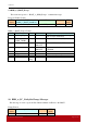
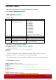
Firmware Version (HEX) = 41 43 52 31 32 38 31 53 20 56 31 30 33
Firmware Version (ASCII) = “ACR1281S V103”
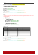
3. Enter Firmware Upgrade Mode
Command = {FF 00 00 E0 00}
Response = {FF 00 00 E1 02 90 00}
Example:
Command: 02 6B 05 00 00 00 01 00 00 00 00 FF 00 00 E0 00 70 03
ACK:
02 00 00 03
Response: 02 83 07 00 00 00 01 00 00 00 00 FF 00 00 E1 02 90 00 09 03
Hints:
After the response display, the reader will enter the firmware upgrade mode that the reader can be
upgraded firmware.
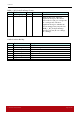
4. LED Control
Setting the LED State:
APDU Command = {E0 00 00 29 01 “CMD”}.
APDU Response = {E1 00 00 00 01 “Status”}
Reading the existing LED State:
APDU Command = {E0 00 00 29 00}.
APDU Response = {E1 00 00 00 01 “Status”}
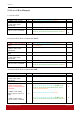
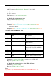
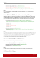
CMD Bit Map
CMD Description Description
Bit 0 RED LED 1 = ON; 0 = OFF
Bit 1 GREEN LED 1 = ON; 0 = OFF
Bit 2 RFU RFU
Bit 3 RFU RFU
Bit 4 RFU RFU
Bit 5 RFU RFU
Bit 6 RFU RFU
Bit 7 RFU RFU
The “Status” bit map is the same as “CMD”.
Example: Red LED ON
Command: 02 6B 06 00 00 00 01 00 00 00 00 E0 00 00 29 01 01 A5 03
ACK:
02 00 00 03
Response: 02 83 06 00 00 00 01 00 00 81 00 E0 00 00 00 01 01 E5 03