
User's Manual


ACR122L-ACS Design Specification
Version 0.03 19/05/2010
Page
6
of
50
ACR122L
-
ACS
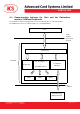
3.0. Hardware Interfaces
3.1. Serial Interface
The ACR122L is connected to a Host through the RS232C Serial Interface at 9600 bps and 115200
bps. 8-N-1
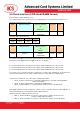
Pin Signal Function
1 VCC
+5V power supply for the reader (Max 200mA, Normal 100mA)
2 TXD
The signal from the reader to the host.
3 RXD
The signal from the host to the reader.
4 GND
Reference voltage level for power supply
3.2. LEDs
• 4 x User-controllable single color LEDs
• Can select control by firmware or by User
• From Left to right, the color of the LED is: Green, Blue, Yellow and Red
3.3. Buzzer
• User-controllable Mono-Tone buzzer.
• The default Buzzer State is OFF
3.4. SAM Interface
• 3 x SAMs socket is provided.
• Support ISO7816 Parts 1-3 T=0 cards
3.5. LCD
• User-controllable LCD
• User-controllable Yellow-Green Backlight
• 2 Line x 16 Character, 5 x 8 dot matrix, STN Yellow Green LCD Type
• 6 O’clock view angle
3.6. Built-in Antenna
• 3 turns symmetric loop antenna. Center tapped.
• The estimated size = 46mm x 64mm.
• The loop inductance should be around ~ 1.6uH to 2.5uH
• Operating Distance for different Tags ~ up to 50mm (depend on the Tag)
• Only one Tag can be accessed at any one time.