
User's Manual

ACR122L-ACS Design Specification
Version 0.03 19/05/2010
Page
25
of
50
ACR122L
-
ACS
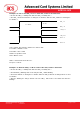
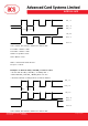
0x02: The buzzer will turn on during the T2 Duration
0x03: The buzzer will turn on during the T1 and T2 Duration.
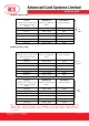
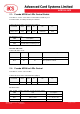
Data Out: SW1 SW2. Status Code returned by the reader.
Table 2.0D: Status Code
Results
SW1 SW2 Meaning
Success 90 Current LED State The operation is completed successfully.
Error
63 00 The operation is failed.
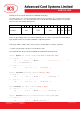
Table 3.0E: Current LED State (1 Byte)
Status Item Description
Bit 0 Current LED_1 LED 1 = On; 0 = Off
Bit 1 Current LED_0 LED 1 = On; 0 = Off
Bits 2 – 7 Reserved
Remark:
1. The LED State operation will be performed after the LED Blinking operation is completed.
2. The LED will not be changed if the corresponding LED Mask is not enabled.
3. The LED will not be blinking if the corresponding LED Blinking Mask is not enabled. Also, the
number of repetition must be greater than zero.
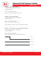
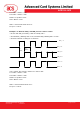
4. T1 and T2 duration parameters are used for controlling the duty cycle of LED blinking and Buzzer
Turn-On duration.
For example, if T1=1 and T2=1, the duty cycle = 50%. #Duty Cycle = T1 / (T1 + T2).
5. To control the buzzer only, just set the P2 “LED State Control” to zero.
6. The make the buzzer operating, the “number of repetition” must greater than zero.
7. To control the LED only, just set the parameter “Link to Buzzer” to zero.