
User's Manual

ACR122L-ACS Design Specification
Version 0.03 19/05/2010
Page
24
of
50
ACR122L
-
ACS
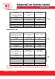
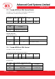
5.2. Pseudo APDU for LEDs and Buzzer Control
This APDU is used to control the states of the LED_0, LED_1 and Buzzer.
Table 2.0A: LED_0, LED_1 and Buzzer Control Command Format (9 Bytes)
Command
Class INS P1 P2 Lc Data In
(4 Bytes)
LEDs and
Buzzer
LED Control
0xFF 0x00 0x40 LED
State
Control
0x04 Blinking Duration Control
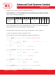
P2: LED State Control
Table 2.0B: LED_0, LED_1 and Buzzer Control Format (1 Byte)
CMD Item Description
Bit 0 Final LED_1 State 1 = On; 0 = Off
Bit 1 Final LED_0 State 1 = On; 0 = Off
Bit 2 LED_1 State Mask 1 = Update the State
0 = No change
Bit 3 LED_0 State Mask 1 = Update the State
0 = No change
Bit 4 Initial LED_1 Blinking State 1 = On; 0 = Off
Bit 5 Initial LED_0 Blinking State 1 = On; 0 = Off
Bit 6 LED_1 Blinking Mask 1 = Blink
0 = Not Blink
Bit 7 LED_0 Blinking Mask 1 = Blink
0 = Not Blink
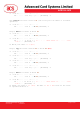
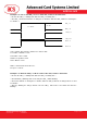
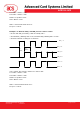
Data In: Blinking Duration Control
Table 2.0C: LED_0, LED_1 Blinking Duration Control Format (4 Bytes)
Byte 0 Byte 1 Byte 2 Byte 3
T1 Duration
Initial Blinking State
(Unit = 100ms)
T2 Duration
Toggle Blinking State
(Unit = 100ms)
Number of
repetition
Link to Buzzer
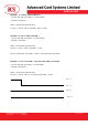
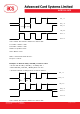
Byte 3: Link to Buzzer. Control the buzzer state during the LED Blinking.
0x00: The buzzer will not turn on
0x01: The buzzer will turn on during the T1 Duration