ACR1222U Technical Specification V1.02 Advanced Card Systems Ltd.
Revision History Rev Number Date Author V1.01 17/12/2009 V1.02 30/09/2010 Vincent Zhong Teddy Liu Vincent Zhong Kit Au Advanced Card Systems Ltd.
INDEX Index ....................................................................................................................................................3 Scopes ..................................................................................................................................................5 Hightlights ...........................................................................................................................................5 Terms ....................................
2.3 Read Binary Blocks .................................................................................................................33 2.4 Update Binary Blocks ..............................................................................................................34 2.5 Value Block Related Commands .............................................................................................35 2.5.1 Value Block Operation ..............................................................................
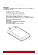
SCOPES This document describes the contactless part (PICC & PCD) of the ACR1222U reader only. HIGHTLIGHTS The ACR1222U is a dual-interface reader (IFD and PCD) that supports both contact (ICC) and contactless (PICC) smart cards. • • • • • • • • • • • • One standard ICC landing type card acceptor. One SAM socket is provided for highly secure applications. A built-in antenna for PICC contactless access applications. ISO 7816 Parts 1-4 Compliant for Contact Smart Card Interface.
TERMS • • • • • • • • • • • • • • • • • • • • • IFD: Interface Device. A terminal, communication device, or machine to which the integrated circuit(s) card is electrically connected during operation. PCD: Proximity Coupling Device. ISO 14443 Contactless Reader. ICC: Integrated Circuit(s) Card. Refer to a plastic card containing an integrated circuit, which is compatible with ISO 7816. SAM: Security Access Module, similar to ICC but in smaller size. PICC: Proximity Integrated Circuit(s) Card.
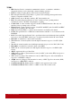
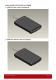
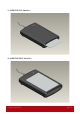
QUICK OVERVIEW OF THE ACR1222U READER 1. ACR1222U (with Contact Card Option) 2. ACR1222U (without Contact Card Option) Advanced Card Systems Ltd.
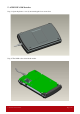
3. ACR1222U ICC Interface 4. ACR1222U PICC Interface Advanced Card Systems Ltd.
5. ACR1222U SAM Interface Step 1: Open the plastic covers by unscrewing the four screws first Step 2: The SAM socket is inside the reader. Advanced Card Systems Ltd.
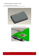
6. ACR1222U Firmware Upgrade Procedure Step 1: Unplug the USB Cable from the PC. Step 2: Open the plastic covers by unscrewing the four screws first. The Button Used For Firmware Upgrade Advanced Card Systems Ltd.
Step 3: Insert the USB plug to USB Port before pressing the button. Step 4: The USB Mass Storage Device can be found in Device Manager. Step 5: Execute the Firmware Upgrade Program: “FW Upgrade Tool.exe” Advanced Card Systems Ltd.
Step 6: Pressing the “Load BIN” Button. Select the “Firmware” file for Upload to the Reader Step 7: Pressing the “Start Program” Button. Start Program The firmware is being uploaded to the reader Advanced Card Systems Ltd.
The firmware upgrade is completed. Step 8: Close the plastic covers. After that, reconnect the USB cord. Noted: If the upgrade firmware “fail”, please repeat do from steps 3 to 7. Advanced Card Systems Ltd.
SYSTEM DESCRIPTION 1. The Reader Block Diagram Advanced Card Systems Ltd.
2. Communication between the PCSC Driver and the ICC, PICC & SAM PCSC Driver ACR1222U PCSC SAM ACR1222U PCSC ICC ACR1222U PCSC PICC ACR1222U ICCs and PICC Advanced Card Systems Ltd.
3. Smart Card Readers Interfaces Overview. Advanced Card Systems Ltd.
HARDWARE DESCRIPTION 1. LED Indicatior The LEDs are used for showing the state of the contact and contactless interfaces.The Red LED is used for showing PICC status and Green LED for ICC. Reader States 1. No PICC Found or PICC present but not activated. 2. PICC is present and activated 3. PICC is operating 4. ICC is present and activated 5. ICC is absent or not activated 6. ICC is operating Red LED PICC Indicator A single pulse per ~ 5 seconds ON Blinking Green LED ICC Indicator ON OFF Blinking 2.
3. USB Interface The ACR1222U is connected to a computer through USB interface as specified in the USB Specification 2.0. The ACR1222U is working in full speed mode, i.e. 12 Mbps. USB Interface Wiring Pin Signal Function 1 VBUS +5V power supply for the reader (~200mA) 2 D- Differential signal transmits data between ACR1222U and PC. 3 D+ Differential signal transmits data between ACR1222U and PC.
SOFTWARE DESCRIPTION 1. TAPDUDemoCard Demo App This program is used to demonstrate the PCSC functions of the ACR1222U readers. Operating Procedures: 1) Place a PICC on the top of the ACR1222U reader. 2) Press “1. Select Reader” and select the “ACR1222 PICC Interface” 3) Select “T1” in the connection-protocol. Press “2. Connect “to establish a connection between the card and reader. 4) Enter the APDU in text box “Message to the card” 5) Press “3. Transmit” to send the APDU to the card. 6) Press “4.
2. ACR1222U PCSC Direct Command Test This program is used to demonstrate the PCSC Escape functions of the ACR1222U readers. Operating Procedures: 1. Select the “ACS ACR1222 SAM Interface 0”. 2. Select the “Shared Mode” if a SAM is inserted or “Direct Mode if no Sam is inserted. 3. Press the button “Connect” to establish a connection between the PC and the ACR1222U reader. 4. Enter “2079” in the Command Text Box. 5. Enter the PCSC Escape Command, e.g.
PERIPHERALS CONTROL The reader’s peripherals control is implemented by Escape Command. 1. Get Firmware Version Command = {18 00} Response = {E1 00 00 00 “Frame Length” {Firmware Version} } In which, Firmware Version = 20 bytes; RFU = 10 bytes e.g. Response = E1 00 00 00 0D 41 43 52 31 32 32 32 55 5F 56 31 30 32 Firmware Version (HEX) = 41 43 52 31 32 32 32 55 5F 56 31 30 32 Firmware Version (ASCII) = “ACR1222U_V102” 2. LED Control Setting the LED State: Command = {29 01 “CMD”}.
3. Buzzer Control Setting the Buzzer State: Command = {28 01 “Duration”} Unit = 10mS 00 = Turn off 01 – FE = Duration FF = Turn on Response = {E1 00 00 00 01 “Status”} Reading the existing Buzzer State: Command = {28 00} Response = {E1 00 00 00 01 “Status”} 4.
5. Refresh the Interface Status Read the existing status: Command = {2D 00} Response = {E1 00 00 00 01 “Interfaces refreshed”} Refresh Interface: Command = {2D 01 “Interfaces to be refreshed”} Response = {E1 00 00 00 01 “Interfaces refreshed”} Bit 0 = ICC Interface Bit 1 = PICC Interface Bit 2 = SAM Interface Hints: This command is useful for refreshing the SAM status after a new SAM is inserted. (* Only Can Use if have SAM inserted before Power-up the reader*) Example 1.
7. Set the PICC Operating Parameter This command is used to control the PICC Operating Parameter of the reader. Read the existing status: Command = {20 00} Response = {E1 00 00 00 01 “PICC Operating Parameter”} Setting the PICC Operating Parameter: Command = {20 01 “CMD”} Response = {E1 00 00 00 01 “PICC Operating Parameter”} PICC Operating Parameter. Default Value = FF Parameter CMD ISO14443 Type A #To detect the MIFARE Bit0 Tags, the Auto ATS Generation must be disabled first.
PICC INTERFACE DESCRIPTION 1. ATR Generation If the reader detects a PICC, an ATR will be sent to the PCSC driver for identifying the PICC. 1.1 ATR format for ISO 14443 Part 3 PICCs. Byte Value Designation (Hex) 0 3B Initial Header 1 8N T0 2 80 TD1 3 01 TD2 80 T1 Tk 3+N 4F 0C RID 4+N SS C0 .. C1 00 00 00 00 UU 4 To RFU TCK Description Higher nibble 8 means: no TA1, TB1, TC1 only TD1 is following.
1.2 ATR format for ISO 14443 Part 4 PICCs. Byte Value Designation (Hex) 0 3B Initial Header 1 8N T0 2 80 TD1 3 01 TD2 4 to 3+N XX XX XX XX T1 Tk Description Higher nibble 8 means: no TA1, TB1, TC1 only TD1 is following. Lower nibble N is the number of historical bytes (HistByte 0 to HistByte N-1) Higher nibble 8 means: no TA2, TB2, TC2 only TD2 is following. Lower nibble 0 means T = 0 Higher nibble 0 means no TA3, TB3, TC3, TD3 following.
PSEUDO APDUS FOR CONTACTLESS INTERFACE ACR1222U comes with two primitive commands for this purpose. 1. Direct Transmit To send a Pseudo APDU (PN532 and TAG Commands), and the Response Data will be returned. Table 1.0A: Direct Transmit Command Format (Length of the PN532_TAG Command + 5 Bytes) Command Class INS P1 P2 Lc Data In Direct Transmit 0xFF 0x00 0x00 0x00 Number of Bytes to send PN532_TAG Command Lc: Number of Bytes to Send (1 Byte) Maximum 255 bytes.
PICC COMMANDS FOR GENERAL PURPOSES 1. Get Data The “Get Data command” will return the serial number or ATS of the “connected PICC”. Table 1.1-1a: Get UID APDU Format (5 Bytes) Command Class INS Get Data FF CA P1 P2 Le 00 01 00 00 (Max Length) Table 2.1-1b: Get UID Response Format (UID + 2 Bytes) if P1 = 0x00 Response Data Out Result UID (LSB) UID (MSB) SW1 SW2 Table 2.1-1c: Get ATS of a ISO 14443 A card (ATS + 2 Bytes) if P1 = 0x01 Response Data Out Result ATS Table 2.
PICC COMMANDS (T=CL EMULATION) FOR MIFARE 1K/4K MEMORY CARDS 2.1 Load Authentication Keys The “Load Authentication Keys command” will load the authentication keys into the reader. The authentication keys are used to authenticate the particular sector of the Mifare 1K/4K Memory Card. Two kinds of authentication key locations are provided, volatile and non-volatile key locations respectively. Table 2.
2.2 Authentication for MIFARE 1K/4K The “Authentication command” uses the keys stored in the reader to do authentication with the MIFARE 1K/4K card (PICC). Two types of authentication keys are used, TYPE_A and TYPE_B respectively. Table 2.2-1a: Load Authentication Keys APDU Format (6 Bytes) #Obsolete Command Class INS P1 P2 P3 Authentication FF 88 00 Block Number Key Type Table 2.
Table 2.2-1c: Load Authentication Keys Response Codes Results SW1 SW2 Meaning Success 90 00 Error 63 00 The operation is completed successfully. The operation is failed. MIFARE 1K Memory Map. Sectors (Total 16 sectors. Each sector consists of 4 consecutive blocks) Sector 0 Sector 1 .. .. Sector 14 Sector 15 Data Blocks (3 blocks, 16 bytes per block) Trailer Block (1 block, 16 bytes) 0x00 ~ 0x02 0x04 ~ 0x06 0x03 0x07 0x38 ~ 0x0A 0x3C ~ 0x3E 0x3B 0x3F Sectors (Total 32 sectors.
Examples: // To authenticate the Block 0x04 with a {TYPE A, key number 0x00}. // PC/SC V2.01, Obsolete APDU = {FF 88 00 04 60 00}; // To authenticate the Block 0x04 with a {TYPE A, key number 0x00}. // PC/SC V2.07 APDU = {FF 86 00 00 05 01 00 04 60 00} Hints: MIFARE Ultralight does not need to do any authentication. The memory is free to access. MIFARE Ultralight Memory Map.
2.3 Read Binary Blocks The “Read Binary Blocks command” is used for retrieving a multiple of “data blocks” from the PICC. The data block/trailer block must be authenticated first before executing the “Read Binary Blocks command”. Table 2.3-1a: Read Binary APDU Format (5 Bytes) Command Class INS P1 Read Binary Blocks FF B0 00 P2 Le Block Number Number of Bytes to Read Block Number (1 Byte): The starting block.
2.4 Update Binary Blocks The “Update Binary Blocks command” is used for writing a multiple of “data blocks” into the PICC. The data block/trailer block must be authenticated first before executing the “Update Binary Blocks command”. Table 2.3-1a: Update Binary APDU Format (Multiple of 16 + 5 Bytes) Command Class INS P1 P2 Lc Update Binary Blocks FF D6 00 Block Number Number of Bytes to Update Data In Block Data (Multiple of 16 Bytes) Block Number (1 Byte): The starting block to be updated.
2.5 Value Block Related Commands The data block can be used as value block for implementing value-based applications. 2.5.1 Value Block Operation The “Value Block Operation command” is used for manipulating value-based transactions. E.g. Increment a value of the value block etc. Table 2.5.1-1a: Value Block Operation APDU Format (10 Bytes) Command Class INS P1 P2 Lc Value Block Operation FF D7 00 Block Number 05 Data In VB_OP VB_Value (4 Bytes) {MSB ..
2.5.2 Read Value Block The “Read Value Block command” is used for retrieving the value from the value block. This command is only valid for value block. Table 2.5.2-1a: Read Value Block APDU Format (5 Bytes) Command Class INS P1 P2 Read Value Block FF B1 00 Le Block Number 00 Block Number (1 Byte): The value block to be accessed. Table 2.5.2-1b: Read Value Block Response Format (4 + 2 Bytes) Response Data Out Result Value {MSB .. LSB} SW1 SW2 Value (4 Bytes): The value returned from the card.
2.5.3 Restore Value Block The “Restore Value Block command” is used to copy a value from a value block to another value block. Table 2.5.3-1a: Restore Value Block APDU Format (7 Bytes) Command Class INS P1 P2 Value Block Operation FF D7 00 Source Block Number Lc 02 Data In 03 Target Block Number Source Block Number (1 Byte): The value of the source value block will be copied to the target value block. Target Block Number (1 Byte): The value block to be restored.
Examples: // Store a value “1” into block 0x05 APDU = {FF D7 00 05 05 00 00 00 00 01} // Read the value block 0x05 APDU = {FF B1 00 05 00} // Copy the value from value block 0x05 to value block 0x06 APDU = {FF D7 00 05 02 03 06} // Increment the value block 0x05 by “5” APDU = {FF D7 00 05 05 01 00 00 00 05} BASIC PROGRAM FLOW FOR CONTACTLESS APPLICATIONS Step 0. Start the application. The reader will do the PICC Polling and scan for tags continuously.
1. How to access PCSC Compliant Tags (ISO14443-4)? Basically, all ISO 14443-4 complaint cards (PICCs) would understand the ISO 7816-4 APDUs. The ACR1222U Reader just has to communicate with the ISO 14443-4 complaint cards through exchanging ISO 7816-4 APDUs and Responses. ACR1222U will handle the ISO 14443 Parts 1-4 Protocols internally. MIFARE 1K, 4K, MINI and Ultralight tags are supported through the T=CL emulation. Just simply treat the MIFARE tags as standard ISO14443-4 tags.
Typical sequence may be: - Present the Tag and Connect the PICC Interface - Read / Update the memory of the tag Step 1) Connect the Tag The ATR of the tag is 3B 8C 80 01 50 00 05 70 3B 00 00 00 00 33 81 81 20 In which, The ATQB = 50 00 05 70 3B 00 00 00 00 33 81 81. It is an ISO14443-4 Type B tag. Step 2) Send an APDU, Get Challenge. << 00 84 00 00 08 >> 1A F7 F3 1B CD 2B A9 58 [90 00] Hint: For ISO14443-4 Type A tags, the ATS can be obtained by using the APDU “FF CA 01 00 00” Advanced Card Systems Ltd.
For Example: ISO7816-4 APDU // To read 8 bytes from an ISO 14443-4 Type B PICC (ST19XR08E) APDU ={80 B2 80 00 08} Class = 0x80 INS = 0xB2 P1 = 0x80 P2 = 0x00 Lc = None Data In = None Le = 0x08 Answer: 00 01 02 03 04 05 06 07 [$9000] Advanced Card Systems Ltd.
2. How to access DESFIRE Tags (ISO14443-4)? The DESFIRE supports ISO7816-4 APDU Wrapping and Native modes. Once the DESFire Tag is activated, the first APDU sent to the DESFire Tag will determine the “Command Mode”. If the first APDU is “Native Mode”, the rest of the APDUs must be in “Native Mode” format. Similarly, If the first APDU is “ISO7816-4 APDU Wrapping Mode”, the rest of the APDUs must be in “ISO7816-4 APDU Wrapping Mode” format. Example 1: DESFIRE ISO7816-4 APDU Wrapping.
Example 3: DESFIRE Native Command. // We can send Native DESFire Commands to the reader without ISO7816 wrapping if we find that the Native DESFire Commands are more easier to handle. // To read 8 bytes random number from an ISO 14443-4 Type A PICC (DESFIRE) APDU = {0A 00} Answer: AF 25 9C 65 0C 87 65 1D D7[$1DD7] In which, the first byte “AF” is the status code returned by the DESFire Card. The Data inside the blanket [$1DD7] can simply be ignored by the application.
[13] is the length of the Pseudo Data “D4 40 01.. 80 00” D4 40 01 is the Data Exchange Command >> D5 41 00 1D 07 [8-byte NFC ID] 00 00 01 00 AA 55 AA 55 AA 55 AA 55 AA 55 AA 55 AA 55 AA [90 00] In which, D5 41 00 is the Data Exchange Response Hint: The NFC ID can be obtained by using the APDU “FF CA 00 00 00” #please refer to the FeliCa specification for more detailed information. 4. How to access NFC Forum Type 1 Tags (ISO18092)? E.g.
#please refer to the Jewel and Topaz specification for more detailed information. FCC Warning: Any Changes or modifications not expressly approved by the party responsible for compliance could void the user's authority to operate the equipment. This device complies with part 15 of the FCC Rules.
TECHNICAL SPECIFICATION Universal Serial Bus Interface Power source ........................................ From USB Speed ................................................... 12 Mbps (Full Speed) Supply Voltage...................................... Regulated 5V DC Supply Current ..................................... 200mA (max); 100mA (normal) Contactless Smart Card Interface Standard ............................................... ISO 14443 A & B Parts 1-4 Protocol ......................................