
User's Manual

ACR122L
-
USB
-
ACS
3.0. Hardware Interfaces
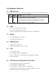
3.1. USB Interface
The ACR122L-USB is connected to computer through USB as specified in the USB Specification 2.0.
ACR122L-USB is working in Full speed mode, i.e. 12 Mbps.
Pin Signal Function
1 V
BUS
+5V power supply for the reader (~ 200mA)
2 D-
Differential signal transmits data between ACR122L-USB and PC.
3 D+
Differential signal transmits data between ACR122L-USB and PC.
4 GND
Reference voltage level for power supply
3.2. LEDs
• 4 x User-controllable single color LEDs
• Can select control by firmware or by User
• From Left to right, the color of the LED is: Green, Blue, Yellow and Red
3.3. Buzzer
• User-controllable Mono-Tone buzzer.
• The default Buzzer State is OFF
3.4. SAM Interface
• 3 x SAMs socket is provided.
• Support ISO7816 Parts 1-3 T=0 ,T=1 cards
3.5. LCD
• User-controllable LCD
• User-controllable Yellow-Green Backlight
• 2 Line x 16 Character, 5 x 8 dot matrix, STN Yellow Green LCD Type
• 6 O’clock view angle
3.6. PICC Interface (Contactless Smart Card)
• 3 turns symmetric loop antenna. Center tapped.
• The estimated size = 46mm x 64mm.
• The loop inductance should be around ~ 1.6uH to 2.5uH
• Operating Distance for different Tags ~ up to 50mm (depend on the Tag)
• Only one Tag can be accessed at any one time.