
User's Manual


ACR122L
-
USB
-
ACS
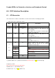
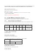
Status Code returned by the reader.
Table 1.0C: Status Code
Results
SW1 SW2 Meaning
Success 90 00 The operation is completed successfully.
Error
63 00 The operation is failed.
Checksum Error
63 27 The checksum of the Response is
wrong.
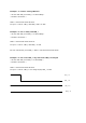
6.2.2. Direct Transmit via ScardControl
Command = {E0 00 00 24 XX “PN532_TAG Command”}
Response = {E1 00 00 00 YY “PN532_TAG Response”}
XX = Length of the “PN532_TAG Command”
YY= Length of the “PN532_TAG Response”
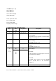
6.3. Pseudo APDU for Peripherals Control
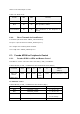
6.3.1. Pseudo APDU for LEDs and Buzzer Control
This APDU is used to control the states of the LED_0, LED_1 and Buzzer.
Table 2.0A: LED_0, LED_1 and Buzzer Control Command Format (9 Bytes)
Command
Class INS P1 P2 Lc Data In
(4 Bytes)
LEDs and
Buzzer
LED Control
0xFF 0x00 0x40 LED
State
Control
0x04 Blinking Duration Control
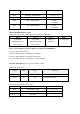
P2: LED State Control
Table 2.0B: LED_0, LED_1 and Buzzer Control Format (1 Byte)
CMD Item Description
Bit 0 Final LED_1 State 1 = On; 0 = Off
Bit 1 Final LED_0 State 1 = On; 0 = Off
Bit 2 LED_1 State Mask 1 = Update the State
0 = No change
Bit 3 LED_0 State Mask 1 = Update the State