
Care and Maintenance Instructions


23
AAC — BLACK RIFLE MANUAL
FIGURE 38
FIGURE 39
FIGURE 37
FIGURE 36
FIGURE 40
FIGURE 35
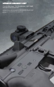
SIDE RAIL AREA
BOLT ASSEMBLY
WARNING! Unload the firearm before lubricating. Look
into the ejection port and visually check the chamber
and magazine to make sure there are no cartridges in
the firearm. Always wear eye protection when handling,
disassembling and reassembling the firearm. Failure to
follow these instructions may cause property damage,
personal injury and/or death.
1. Always keep the firearm pointed in a safe direction.
2. Remove the magazine, pull and hold the bolt fully
rearward to inspect the chamber. See Figure
11. Visually and physically verify the Chamber is
completely unloaded See the section “Clearing/
Unloading Your Rifle”.
3. Disassemble the firearm per the instructions in the
“Disassembling Your Firearm,” section of this manual.
4. Inspect, clean and lubricate the firearm per the
instructions in the “Inspect/Cleaning/Lubricating,”
section of this manual.
5. Lightly lubricate the Firing Pin and the Firing Pin
recess in the Bolt with oil.
6. Generously lubricate the Bolt, its Cam Pin area and
the Bolt Gas Rings. A lighter application is good on the
Extractor and its Pin.
7. Lightly lubricate the Charging Handle and its Latch
and Spring.
8. Lightly lubricate the inner and outer surfaces of the
Bolt Carrier. Generously lubricate the Cam Pin area
and the “Slide” Rail areas of the Bolt Carrier where
they contact the inside of the Receiver. (Figure 40)
9. The inside of the Carrier Key on the Bolt Carrier should
be dried with a Q-Tip or Pipe Cleaner - then place one
drop of CLP inside.
REASSEMBLING YOUR RIFLE
WARNING! Before reassembling your firearm, make
sure it is completely unloaded (both the chamber and
the magazine) and engage the safety mechanism by
placing the safety lever in the “S” or "SAFE" position.
Failure to follow these instructions may cause property
damage, personal injury and/or death.
WARNING! No components/parts may be left out of
the reassembly of your firearm. Failure to use all the
components/parts and assemble them properly may
cause property damage, personal injury and/or death.
FIGURE 41
1. Always keep the firearm pointed in a safe direction.
2. Remove the magazine, pull and hold the bolt fully
rearward to inspect the chamber. See Figure
11. Visually and physically verify the Chamber is
completely unloadedSee the section “Clearing/
Unloading Your Rifle”.
3. Disassemble the firearm per the instructions in the
“Disassembling Your Firearm,” section of this manual.
4. Inspect, clean and lubricate the firearm per the
instructions in the “Inspect/Cleaning/Lubricating,”
section of this manual.
5. Ensure the Hammer is fully cocked and the safety
lever is in the “Safe” position.
6. Depress the Buffer Retainer and insert the Action
Spring and Buffer.
7. Insert Extractor and Extractor Spring into the Bolt.
NOTE: Extractor Assembly has a Rubber Insert within
the Extractor Spring. If the Extractor Spring comes
loose, put the large end of the Extractor Spring in the
extractor and seat it by pushing down on the Rubber
Insert (a Bullet tip works well). See Figure 35.
8. Firmly push the Extractor into the bolt to compress
the Extractor Spring and reinsert Extractor Pin.
9. Press the rear of the Extractor to check the Extractor
Spring Function. The Extractor should return to its
original position when the pressure is removed.
10. Insert Bolt into Bolt Carrier.
11. Twist the Bolt to align the Cam Pin Hole in the Bolt
with the Cam Profile in the Bolt carrier.
12. Insert the Cam Pin in the Bolt Assembly. See
Figure 36.
NOTE: The Cam Pin can only be installed in Bolt from one
side, if it does not t, twist the Bolt 180° and try again.
13. Once Cam Pin is fully inserted, twist it 90° (this will
allow insertion of the Firing Pin).
WARNING! The cam pin must be installed in the Bolt
Assembly. Use of a Bolt Assembly without the Cam
Pin may cause property damage, personal injury and/
or death.
14. Insert the Firing Pin into the Bolt Assembly. See
Figure 24.
15. Pull Bolt fully forward of the Bolt Carrier. See
Figure 37.
16. Reinsert the Firing Pin Retaining Pin. See Figure 38.
NOTE: After reinserting Firing Pin Retaining Pin, the
Firing Pin should not fall out when Bolt Carrier Group is
turned with the bolt facing up.
WARNING! Do not interchange bolts between different
firearms. Using an improper bolt with your firearm may
cause property damage, personal injury and/or death.
17. Insert Charging Handle into Upper Receiver and
lower the “ears” at front end of Handle into cutouts
in Upper Receiver.
18. If the Ejection Port Cover is closed, open it.
19. Slide Charging Handle partially into the
Upper Receiver.
20. Insert the complete Bolt Carrier Assembly into
Upper Receiver. The Gas Key will fit into groove in
the Charging Handle. See Figure 39.
NOTE: If the Bolt is not fully pulled forward of the Bolt
Carrier when the assembly is inserted into the Upper
Receiver, the Cam Pin will hit the receiver, preventing
assembly.
21. Slide the Bolt Carrier Assembly and Charging
Handle fully into the Upper Receiver. The Charging
Handle Latch will lock onto the Upper Receiver.
22. To join the Upper and Lower Receivers, position the
Pivot Pin Lug of Upper Receiver into slot at front of
Lower Receiver and push Pivot Pin into place. See
Figure 40.
23. Pivot the Upper Receiver onto the Lower receiver
until they are fully mated, push in Takedown Pin.
See Figure 41.
NOTE: Pivot Pin and Takedown Pin are captured in the
Lower Receiver, preventing them from falling out and
becoming lost.
24. Conduct a function check per the steps shown in
the “Safety Function Check,” section of this manual.