
User's Manual


Note: You should connect this wire if you program the Start Feature E – 2 to “Tachometer checking type”, otherwise do not
connect this wire and tap the end.
Note: No connection of this wire is required, if you use the voltage or timer checking type mode.
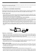
This input provides the remote start system with information about the engine’s revolutions per minute (RPM). It can be
connected to the negative side of the coil in vehicle with conventional coils. In multi-coil and high energy ignition system locating
a proper signal may be more difficult. Once connected,
To test for a tachometer wire, a multi-meter capable of testing AC voltage must be used. The tachometer wire will show between
1V and 6V AC at idle, and will increase as engine RPM increases. In multi-coil ignition system, the system can learn individual
coil wire. Individual coil wires in a multi-coil ignition system will register lower amounts of AC voltage. Also, if necessary, the
system can use a fuel injector control wire for engine speed sensing. Common locations for a tachometer wire are the ignition
coil itself, the back of the gauges, engine computers, and automatic transmission computers.
IMPORTANT! Do not test tachometer wires with a test light or logic probe. The vehicle will be damaged.
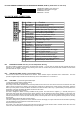
How to find a tachometer wire with your multi-meter
1. Set the ACV or AC voltage (12V or 20V is fine.)
2. Attach the (-) probe of the meter to chassis ground.
3. Start and run the vehicle.
4. Probe the wire you suspect of being the tachometer wire with the red probe of the meter.
5. If this is the correct wire the meter will read between 1V and 6V.
IMPORTANT NOTE: Must program the “Tach Signal” before trying to remote start.
H6/11 BLUE/BLACK WIRE – (-) 200mA Accessory 2 Output –
This wire provides a 200mA (-) ground output. This output will energize when the remote start is activated, go away while the
starter is cranking, and then come back on when the vehicle has started successfully.
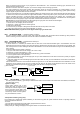
H6/12 WHITE/GREEN WIRE – (-) Diesel Wait To Start Input
(See Start Feature D - 1 Programming)
In diesel vehicles it is necessary to interface with the wire that on the WAIT-TO-START light in the dashboard. This wire
illuminates the bulb until the vehicle’s glow plugs are properly heated. When the light goes out the vehicle can be started. This
wire is always at the connector leading to the bulb in the dashboard. It can also be found at the Engine Control Module (ECM) in
many vehicles.
To test and determine the polarity of this wire:
1. Set your multi-meter to DCV or DC voltage (12V or 20V is fine).
2. Attach the (+) probe of the meter to (+) 12V.
3. Probe the wire that you suspect leads to the bulb with the (-) probe of the meter.
4. Turn the ignition switch to the ON position.
5. If the meter indicates 12 volts until the light goes out you have isolated the connect wire and the wire’s polarity is negative
(ground while the bulb is on).
6. If the meter reads zero volts until the light goes out and then reads 12 volts, you have isolated the connect wire and the wire’s
polarity is positive.
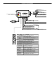
Connect this wire to the wire in the vehicle that sends the signal to turn on the WAIT-TO-START bulb in the dashboard. In most
diesels the wire is negative (ground turns on the bulb) and this wire can be directly connected to the wire in the vehicle. If the
vehicles use a positive wire (12V to turn the bulb) a relay must be used to change the polarity.
(
-
)
Wait To Start Wir
e
Wait to Start
Indicator
Ignition (+)
White/Green Wire
Wait To Start In
p
u
t
87a
86
87
30
85
(
+
)
Wait To Start
Wait To Start
Indicator
White/Green
Wire
Wait To Start In
p
ut
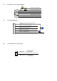
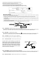
H6/13 YELLOW WIRE – (-) 200mA Ignition 3 Output –
This wire provides a 200mA (-) ground output that becomes active 4 seconds before the remote start unit initialize, and remains
grounded while running.
Ignition 3 output:
Some newer vehicles use a third
ignition wire which is required to start
and keep the vehicle’s engine running.
If this is the case, wire an IGN 3 relay
(not supplied) as shown below: Do not
connect any vehicle circuits together,
they are isolated for a reason.
Y
ellow Wire
87a
Ignition 3 Wire From
Ignition Key Switch
+ 12 V Constant
Fused 25A Capable
30
8586
87
Transponder interfacing using relay:
If the vehicle has a transponder system installed, you will need to by-pass the system while the vehicle is
operating under the
control of the Remote Start Unit.
To do this:
1.You will need a transponder key that's already programmed to the vehicle.
2.Remove the trim around the ignition switch.
3.Wrap a thin (28 - 30awg) wire tightly around ignition switch 6 to 8 times and secure it.