
User's Manual


vehicle’s climate control system. Some vehicles may have separate wires for the blower motor and the air
conditioning compressor. In such cases, it will be necessary to add a relay to power the second accessory wire.
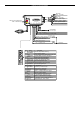
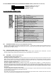
H5: 5 PIN WIRE HARNESS:
RED / WHITE WIRE –PARKING LIGHT RELAY INPUT —
The RED/WHITE wire is the input to the flashing parking light relay. The connection of the RED/WHITE wire will
determine the output polarity of the flashing parking light relay.
If the vehicle you are working on has +12volt switched parking lights, you don’t need connect this wire. This wire is
already connected to +12volt.
If the vehicle’s parking lights are ground switched, cut the RED/WHITE wire, connect the RED/WHITE wire to
chassis ground.
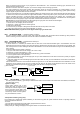
WHITE WIRE — PARKING LIGHT RELAY OUTPUT
(+12 V 10A OUTPUT) —
Connect the WHITE wire to the parking light wire coming from the headlight switch. Do not connect the WHITE wire
to the dashboard lighting dimmer switch. (Damage to the dimmer will result). The limitation of the WHITE wire is 10
AMP max. Do not exceed this limit or damage to the alarm and parking relay will result.
BLACK WIRE — SYSTEM GROUND –
This is the main ground connection of the alarm module. Make this connection to a solid section of the vehicle frame.
Do not connect this wire to any existing ground wires supplied by the factory wire loom, make the connection to the
vehicle’s frame directly.
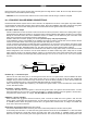
BROWN WIRE – (+) 2A SIREN OUTPUT –
This wire is provides power to the supplied siren. Connect the Brown wire to the Red wire of the siren. Connect the
Black wire of the siren to a stable chassis ground.
RED WIRE — SYSTEM POWER (+12V CONSTANT) —
The RED wire supplies power to the system. Connect this wire to a stable constant +12 volt source.
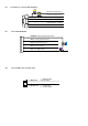
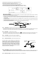
H7. 3-PIN BLACK CONNECTOR. – TWO-WAY TRANSCEIVER/ANTENNA MODULE
The Two-way transceiver/antenna mounting
location should be the upper left or lower left corner
of driver’s windshield. For optimum range we
suggest that the antenna be mounted as shown in
picture to the right. (Antenna tip facing up)
Warning!
Do not mount in such a manner that it obstructs the
driver’s view.
- Remove the protective tape backing.
- Carefully align the two-way transceiver/antenna and apply to windshield.
- Route the black connector wire behind the trim and connect to the two-way transceiver/antenna.
- Connect the other end to the control module.
- Special considerations must be made for windshield glass as some newer vehicles utilize a metal-shielded window glass that
will inhibit or restrict RF reception. In these vehicles, route the two ways transceiver/antenna module away from metallic
shielded window glass as far as possible.
H8. 2 PIN BLUE CONNECTOR FOR THE VALET SWITCH: (Under door on main unit)
Select a mounting location for the switch that is easily accessible to the driver of the vehicle. The switch does not
have to be concealed, however, concealing the switch is always recommended, as this provides an even higher level
of security to the vehicle. Mount the valet switch in a hidden but accessible location. Route the valet switch wires to
the control module.
H3. 2 PIN WHITE CONNECTOR (THE LED STATUS INDICATOR):
The led indicator status should be mounted in a highly visible area such as top of the dashboard, on top of the shifter
console or on the dashboard face. Leave at least 6mm space behind the mounting location for LED housing. Once a
suitable location is chosen, drill a 6mm hole. Run the LED wires through the hole then press the 2 pin LED housing into
place. Route the LED wires to the control module.