
User's Manual
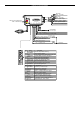
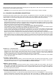


INSTALLATION DIAGRAM
Red : +12v input
Violet : Starter Output
Yellow : Ignition 1 Output
Pink : Ignition 2 Output
Brown : ACC/Heater Output
LED Indicator
Blue : Valet sw Input
Orange : Sensor #1(Zone4)
20A Fuse
White
Black
Black
H2H6
H1
H9
H8
H7
Red : +12v input
20A Fuse
To Car Battary
White : Parking Light Relay Output
Brown Siren(+) Output
Black
System Main Ground
Red +12v Output
Blue
(-) Unlock Pulse,(+) Lock Pulse Output
DB
I
CI3 RS-730
Red : +12v Battery Power
Red/White : Parking Light Relay Power Input
15 A Fuse
3A Fuse
Green
(+) Unlock Pulse,(-) Lock Pulse Output
Black
H3
White
H4
White
H5
Antenna Receiver Assembly(434MHz)
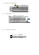
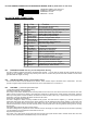
Pin
Color
Function
1
2
3
4
5
6
7
8
9
10
Black/White
Neutral Safety Switch Input
Gray/Black
Second Starter Output
Pink
2-Step Unlock/Factory Disarm/Sensor By-pass
White
Ground Output While Running
Brown/Black
Black/Green
Tachometer Signal Input
Gray
Yellow
Blue/Black
Accessory 2 Control Output
Pin
Function
11
12
13
14
15
16
17
18
19
20
Color
Blue
Zone 2 Negative Hood/Trunk Trigger
White/Green
Instant Start And Turn Off Input
White/Blue
Green
Zone 3 (-) Negative Door Pin Trigger
Violet
White/Red
White/Black
(-) Negative Hood Pin Safety Shutdown
5
10
12
9
8
18
6
19
7
17
2
14
16
4
15
3
13
1
Dome Light Control Output
Ground
Output When Armed
Channel 4 Programmable Output
Channel 3(Trunk) Output
Brown/White
Horn
Output (Programmable)
Diesel Wait To Start Input
Ignition 3 Control Output
Zone 3 (+) Positive Door Pin Trigger
Orange
White/Violet
(+) Brake Switch Shutdown Input
Ground
Output When Disarmed
Orange/White
11
20