
User's Manual
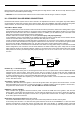


4.About 6"down line make another loop of approximately 2"diameter.
5.Place the key inside this loop and secure it to the loop.
6. Connect on end of the (28 - 30awg) wire to pin (87) of the relay module.
7. Connect the other end of the loop wire to Pin (30) of relay module.
8. Connect the pin (86) of the relay module to the ignition wire from the ignition switch.
9.
Connect the pin (85) of the relay module to the H6/13 yellow wire of 20-pin connector.
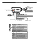
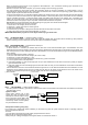
GM VATS KEY OVERRIDE:
If the vehicle has the General Motor VATS system installed, you will need to by-pass the system while the vehicle is operating
under the control of the Remote Start Unit. To do this:
1. Measure the resistance of the resistor pellet on the ignition key then select a resistor within 5% of the key’s value.
2. Locate the pair of VATS wires in the vehicle, usually a pair of thin gauge wires running from the ignition switch to the VATS
control module.
3. Connect the YELLOW wire from Remote Start Unit to TERMINAL #85 of an external relay. Connect terminal #86 of the relay
to a fused +12 volt.
4. Cut (#1) wire (as shown), and connect the ignition switch side of the cut wire to terminal #87a of the relay. Connect the other
side of the (#1) wire to terminal #30.
5. Connect the previously seleted resistor from terminal #87 to the second(#2) wire (as shown).
To + 12 V
Ignition
Switch
YELLOW wire
Matching Resistor
VATS control Module
87a 86
30
87
85
VAT wire (#1)
VAT wire
(
#2
)
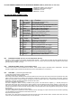
H6/14 GREEN WIRE – Negative Door Switch Sensing Input (Zone 3) –
This wire is the ground trigger input wire for negative door pin switch. This wire is connection for "grounding" type factory door
pins locate the "common wire" that connects the door pin switches. Make the connection of the GREEN Wire here.
H6/15 GRAY WIRE – (-) 200mA Channel 3 Output –
This will become a 1 second pulse ground by activate (button 3)
on transmitter for two seconds, the current capacity of this
wire is 200 mA. This feature allows you to remote control trunk release or other electric device. (Realay may be required).
H6/16 BLUE WIRE – Ground Instant Trigger Input (Zone 2) –
This wire is the ground trigger input wire for hood and or trunk pin switches
H6/17 WHITE/VIOLET WIRE – Positive Safety Shut Down Input –
H6/18 VIOLET WIRE – Positive Door Switch Sensing Input (Zone 3)–
This wire is the positive trigger input wire for positive door pin switch. This wire is connection for "positive" type factory door
pins(typical FORD MOTOR). Locate the "common wire" for all door pins and make the connection of the VIOLET Wire here.
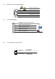
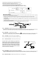
H6/19 WHITE/BLACK WIRE – Negative Safety Shut Down Input – Hood trigger Input
This wire provides an instant shutdown for the remote start,
whenever it gets +12volts. If the brake lights switch in the
vehicle switches +12 volts to the brake light circuit, connect this
wire to the output side of the brake switch. This will allow the
remote start to shut down if an attempt is made to operate the
vehicle without the key while running under the control of the
remote start. In most vehicles, in order to shift gear, the brake
pedal must be depressed. The brake input will in turn cause the
remote start unit to shut off. See diagram.
+12 volts from fuse box
To White/ Violet
wire
Brake light bulbs
Switch closes
When brake is
de
p
ress