User’s Manual Wireless ARM9 4port Full function version with VPN For internal reference only Charlie 20031002
Note: This page should be remove before send to Customer 1. This manual is modified base on 4-port wireless router, so some pictures are 4-port router, You may need to change them to fit your needs. Note: Watch out COM port, and Printer port, if this product doesn’t have them, you have to remove them. 2. Some functions are implemented on specific models only (the blue words) Charlie 20020807 4.
Copyright The contents of this publication may not be reproduced in any part or as a whole, stored, transcribed in an information retrieval system, translated into any language, or transmitted in any form or by any means, mechanical, magnetic, electronic, optical, photocopying, manual, or otherwise, without the prior written permission. Trademarks All product, company, brand names are trademarks or registered trademarks of their respective companies. They are used for identification purpose only.
FCC Interference Statement This equipment has been tested and found to comply with the limits for a Class B digital device, pursuant to Part 15 of the FCC Rules. These limits are designed to provide reasonable protection against harmful interference in a residential installation. This equipment generates, uses and can radiate radio frequency energy and, if not installed and used in accordance with the instructions, may cause harmful interference to radio communications.
Table of Contents Chapter 1 Introduction .............................................................................. 7 Functions and Features ........................................................................ 7 Packing List ......................................................................................... 9 Chapter 2 Hardware Installation ............................................................... 9 2.1 Panel Layout (your product may need to be modified) ................. 9 2.
4.8 Toolbox ........................................................................................ 75 4.8.1 System Log ............................................................................... 76 4.8.2 Firmware Upgrade .................................................................... 77 4.8.3 Backup Setting .......................................................................... 78 4.8.4 Reset to default ......................................................................... 78 4.8.5 Reboot .
Chapter 1 Introduction Congratulations on your purchase of this outstanding Wireless Broadband Router. This product is specifically designed for Small Office and Home Office needs. It provides a complete SOHO solution for Internet surfing, and is easy to configure and operate even for non-technical users. Instructions for installing and configuring this product can be found in this manual.
Packet filter supported Packet Filter allows you to control access to a network by analyzing the incoming and outgoing packets and letting them pass or halting them based on the IP address of the source and destination. Universal Plug and Play (UPnP) supported Universal Plug and Play (UPnP) enable devices such as PCs, routers or other devices to be plugged into a network and automatically know about each other.
VPN Supported Enables you to create virtual private tunnels to remote VPN gateways. L2TP Server L2TP Server enables user to build a virtual private network (VPN) connection from the remote user to the corporate LAN. PPTP Server PPTP Server enables user to build a virtual private network (VPN) connection from the remote user to the corporate LAN. 802.1X supported When the 802.1X function is enable, the Wireless user must Authenticate to this router first to use the Network service.
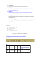
On WAN WAN port activity Wireless Wireless activity Green Blinking Green Blinking On Link/Act. 1~4 Link status Data Rate Green On On USB USB port activity The WAN port is sending or receiving data. Sending or receiving data via wireless An active station is connected to the corresponding LAN port. Green Blinking 10/100 The WAN port is linked. Green Blinking The corresponding LAN port is sending or receiving data. Data is transmitting in 100Mbps on the corresponding LAN port.
Port: RESET To reset system settings to factory defaults, please follow the steps: 1. Power off the device, 2. Press the reset button and hold, 3. Power on the device, 4. Keep the button pressed about 5 seconds, 5. Release the button, 6. Watch the M1 LED, they will flash 8 times and then M1 flash once per second.
2.1.2. Rear Panel Figure 2-2 Rear Panel Ports: Port Description 5VDC Power inlet: DC 5V, 1.5A (minimum) WAN the port where you will connect your cable (or DSL) modem or Ethernet router. Port 1-4 the ports where you will connect networked computers and other devices. USB USB Ports for USB printer. PRINTER Printer Port (Optional) COM Serial port (connect analog modem or console cable)(optional) 2.2 Procedure for Hardware Installation 1.
2. Setup LAN connection a. Wired LAN connection: connects an Ethernet cable from your computer’s Ethernet port to one of the LAN ports of this product. b. Wireless LAN connection: locate this product at a proper position to gain the best transmit performance. Figure 2-3 Setup of LAN and WAN connections for this product. 3. Setup WAN connection Prepare an Ethernet cable for connecting this product to your cable/xDSL modem or Ethernet backbone. Figure 2-3 illustrates the WAN connection. 4.
Chapter 3 Network Settings and Software Installation To use this product correctly, you have to properly configure the network settings of your computers and install the attached setup program into your MS Windows platform (Windows 95/98/NT/2000). 3.1 Make Correct Network Settings of Your Computer The default IP address of this product is 192.168.123.254, and the default subnet mask is 255.255.255.0. These addresses can be changed on your need, but the default values are used in this manual.
Notice: Only Windows 95/98 need to install this Printer Driver. If you are using Windows 2000/XP, please refer to Chapter 5 Printer - 5.2 Configuring on Windows 2000 and XP Platforms. Step 1: Insert the installation CD-ROM into the CD-ROM drive. The following window will be shown automatically. If it isn’t, please run “install.exe” on the CD-ROM.
Step 2: Click on the INSTALL button. Wait until the following Welcome dialog to appear, and click on the Next button. Step 3: Select the destination folder and click on the Next button. Then, the setup program will begin to install the programs into the destination folder.
Step 4: When the following window is displayed, click on the Finish button. Step 5: Select the item to restart the computer and then click the OK button to reboot your computer. Step 6: After rebooting your computer, the software installation procedure is finished. Now, you can configure the NAT Router (refer to Chapter 4) and setup the Print Server (refer to Chapter 5).
Chapter 4 Configuring Wireless Broadband Router This product provides Web based configuration scheme, that is, configuring by your Web browser, such as Netscape Communicator or Internet Explorer. This approach can be adopted in any MS Windows, Macintosh or UNIX based platforms. 4.1 Start-up and Log in Activate your browser, and disable the proxy or add the IP address of this product into the exceptions.
4.2 Status This option provides the function for observing this product’s working status: A. WAN Port Status. If the WAN port is assigned a dynamic IP, there may appear a “Renew” or “Release” button on the Sidenote column. You can click this button to renew or release IP manually. B. Modem Status. C. Printer Status. There two printer types: Printer (DB25) and Printer (USB). The possible kinds of printer status include “Ready”, “Not ready”, “Printing…”, and “Device error”.
4.3 Wizard Setup Wizard will guide you through a basic configuration procedure step by step.
Setup Wizard - Select WAN Type: For detail settings, please refer to 4.4.1 primary setup.
4.
4.4.
This option is primary to enable this product to work properly. The setting items and the web appearance depend on the WAN type. Choose correct WAN type before you start. 1. LAN IP Address: the local IP address of this device. The computers on your network must use the LAN IP address of your product as their Default Gateway. You can change it if necessary. 2. WAN Type: WAN connection type of your ISP. You can click Change button to choose a correct one from the following four options: A.
the lease time is expiring-- even when the system is idle. 4.4.1.3 Dynamic IP Address with Road Runner Session Management.(e.g. Telstra BigPond) LAN IP Address is the IP address of this product. It must be the default gateway of your computers. WAN Type is Dynamic IP Address. If the WAN type is not correct, change it! Host Name: optional. Required by some ISPs, e.g. @Home.
4.4.1.6 Dial-up Network 1. Dial-up Telephone, Account and Password: assigned by your ISP. For security, this field appears blank. If you don't want to change the password, leave it empty. 2. Primary and Secondary DNS: If they are configured as "0.0.0.0.", they will be automatically assigned upon connection. 3. Maximum Idle Time: the amount of time of inactivity before disconnecting your dial-up session. 4. Baud Rate: the communication speed between this product and your MODEM or ISDN TA. 5.
4.4.1.7 Virtual Computers Virtual Computer enables you to use the original NAT feature, and allows you to setup the one-to-one mapping of multiple global IP address and local IP address. • Global IP: Enter the global IP address assigned by your ISP. • Local IP: Enter the local IP address of your LAN PC corresponding to the global IP address. • Enable: Check this item to enable the Virtual Computer feature.
4.4.
The settings of a TCP/IP environment include host IP, Subnet Mask, Gateway, and DNS configurations. It is not easy to manually configure all the computers and devices in your network. Fortunately, DHCP Server provides a rather simple approach to handle all these settings. This product supports the function of DHCP server.
IP to your PC. 4.4.3 Wireless Setting, and 802.1X setting Wireless settings allow you to set the wireless configuration items. 1. Network ID(SSID): Network ID is used for identifying the Wireless LAN (WLAN). Client stations can roam freely over this product and other Access Points that have the same Network ID. (The factory setting is “default”) 2. Channel: The radio channel number. The permissible channels depend on the Regulatory Domain.
802.1X CheckBox was used to switch the function of the 802.1X. When the 802.1X function is enable, the Wireless user must authenticate to this router first to use the Network service. RADIUS Server IP address or the 802.1X server’s domain-name. RADIUS Shared Key Key value shared by the RADIUS server and this router. This key value is consistent with the key value in the RADIUS server.
4.4.4 Change Password You can change Password here. We strongly recommend you to change the system password for security reason.
4.
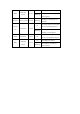
4.5.1 Virtual Server This product’s NAT firewall filters out unrecognized packets to protect your Intranet, so all hosts behind this product are invisible to the outside world. If you wish, you can make some of them accessible by enabling the Virtual Server Mapping. A virtual server is defined as a Service Port, and all requests to this port will be redirected to the computer specified by the Server IP. Virtual Server can work with Scheduling Rules, and give user more flexibility on Access control.
21 192.168.123.1 V 80 192.168.123.2 V 1723 192.168.123.6 V 4.5.2 Special AP Some applications require multiple connections, like Internet games, Video conferencing, Internet telephony, etc. Because of the firewall function, these applications cannot work with a pure NAT router. The Special Applications feature allows some of these applications to work with this product. If the mechanism of Special Applications fails to make an application work, try setting your computer as the DMZ host instead. 1.
Note! At any given time, only one PC can use each Special Application tunnel.
4.5.3 Miscellaneous Items IP Address of DMZ Host DMZ (DeMilitarized Zone) Host is a host without the protection of firewall. It allows a computer to be exposed to unrestricted 2-way communication for Internet games, Video conferencing, Internet telephony and other special applications. NOTE: This feature should be used only when needed. Non-standard FTP port You have to configure this item if you want to access an FTP server whose port number is not 21. This setting will be lost after rebooting.
4.
4.6.1 Packet Filter Packet Filter enables you to control what packets are allowed to pass the router. Outbound filter applies on all outbound packets. However, Inbound filter applies on packets that destined to Virtual Servers or DMZ host only. You can select one of the two filtering policies: 1. Allow all to pass except those match the specified rules 2. Deny all to pass except those match the specified rules You can specify 8 rules for each direction: inbound or outbound.
addresses (4.3.2.1-4.3.2.254). An empty implies all IP addresses. For source or destination port, you can define a single port (80) or a range of ports (1000-1999). Add prefix "T" or "U" to specify TCP or UDP protocol. For example, T80, U53, U2000-2999. No prefix indicates both TCP and UDP are defined. An empty implies all port addresses. Packet Filter can work with Scheduling Rules, and give user more flexibility on Access control. For Detail, please refer to Scheduling Rule.
and browse the Internet (port 80) (1.2.3.10-1.2.3.20) They can do everything (block nothing) Others are all blocked. Example 2: (1.2.3.100-1.2.3.119) They can do everything except read net news (port 119) and transfer files via FTP (port 21) Others are all allowed. After Inbound Packet Filter setting is configured, click the save button. Outbound Filter: To enable Outbound Packet Filter click the check box next to Enable in the Outbound Packet Filter field.
Example 1: (192.168.123.100-192.168.123.149) They are allowed to send mail (port 25), receive mail (port 110), and browse Internet (port 80); port 53 (DNS) is necessary to resolve the domain name. (192.168.123.10-192.168.123.20) They can do everything (block nothing) Others are all blocked.
(192.168.123.100-192.168.123.119) They can do everything except read net news (port 119) and transfer files via FTP (port 21) Others are allowed After Outbound Packet Filter setting is configured, click the save button.
4.6.2 Domain Filter Domain Filter let you prevent users under this device from accessing specific URLs. Domain Filter Enable Checke if you want to enable Domain Filter. Log DNS Query Checke if you want to log the action when someone accesses the specific URLs. Privilege IP Addresses Range Setting a group of hosts and privilege these hosts to access network without restriction. Domain Suffix A suffix of URL to be restricted. For example, ".com", "xxx.com".
Example: In this example: 1. URL include “sex.com” will be blocked, and the action will be record in log-file. 2. URL include “girl.com” will not be blocked, but the action will be record in log-file. 3. URL include “erotica.com” will be blocked, but the action will not be record in log-file. 4. IP address X.X.X.1~ X.X.X.10 can access network without restriction.
4.6.3 URL Blocking URL Blocking will block LAN computers to connect to pre-defined Websites. The major difference between “Domain filter” and “URL Blocking” is Domain filter require user to input suffix (like .com or .org, etc), while URL Blocking require user to input a keyword only. In other words, Domain filter can block specific website, while URL Blocking can block hundreds of websites by simply a keyword. URL Blocking Enable Checked if you want to enable URL Blocking.
In this example: 1.URL include “sex” will be blocked, and the action will be record in log-file. 2.URL include “erotica” will be blocked, but the action will be record in log-file 3.URL include “girl” will not be blocked, but the action will be record in log-file. 4.
4.6.4 MAC Address Control MAC Address Control allows you to assign different access right for different users and to assign a specific IP address to a certain MAC address. MAC Address Control Check “Enable” to enable the “MAC Address Control”. All of the settings in this page will take effect only when “Enable” is checked. Connection control Check "Connection control" to enable the controlling of which wired and wireless clients can connect to this device.
allow or deny the clients, whose MAC addresses are not in the "Control table", to associate to the wireless LAN. Control table "Control table" is the table at the bottom of the "MAC Address Control" page. Each row of this table indicates the MAC address and the expected IP address mapping of a client. There are four columns in this table: MAC Address MAC address indicates a specific client. IP Address Expected IP address of the corresponding client. Keep it empty if you don't care its IP address.
4.6.5 VPN setting VPN Settings are settings that are used to create virtual private tunnels to remote VPN gateways. The tunnel technology supports data confidentiality, data origin authentication and data integrity of network information by utilizing encapsulation protocols, encryption algorithms, and hashing algorithms. • VPN enable item VPN protects network information from ill network inspectors. But it greatly degrades network throughput. Enable it when you really need a security tunnel.
Function of Buttons More: To setup detailer configuration for manual key or IKE approaches by clicking the "More" button. 4.6.5.1 VPN Settings - IKE •VPN Settings - IKE There are three parts that are necessary to setup the configuration of IKE for the dedicated tunnel: basic setup, IKE proposal setup, and IPSec proposal setup. Basic setup includes the setting of following items: local subnet, local netmask, remote subnet, remote netmask, remote gateway, and pre-shared key.
Local netmask combined with local subnet to form a subnet domain. Remote subnet The subnet of LAN site of remote VPN gateway, it can be a host, a partial subnet, and the whole subnet of LAN site of remote gateway. Remote netmask Remote netmask combined with remote subnet to form a subnet domain of remote end. Remote gateway The IP address of remote VPN gateway. Pre-shared key The first key that supports IKE mechanism of both VPN gateways for negotiating further security keys.
•VPN Settings - Set IKE Proposal IKE Proposal index A list of selected proposal indexes from the IKE proposal pool listed below. The selecting activity is performed by selecting a proposal ID and clicking "add to" button in the bottom of the page. There are only four indexes can be chosen from the proposal pool for the dedicated tunnel. Remove button beside the index list can remove selected proposal index before. Proposal name It indicates which IKE proposal to be focused.
4.6.5.3 VPN Settings -Set IPSec Proposal •VPN Settings -Set IPSec Proposal IPSec Proposal index A list of selected proposal indexes from the IPSec proposal pool listed below. The selecting activity is performed by selecting a proposal ID and clicking "add to" button in the bottom of the page. There are only four indexes can be chosen for the dedicated tunnel. Remove button beside the index list can remove selected proposal index before. Proposal name It indicates which IPSec proposal to be focused.
Authentication algorithm There are two algorithms can be selected: SHA1 and MD5. But none also can be selected here for IPSec proposal. Life time The unit of life time is based on the value of Life Time Unit. If the value of unit is second, the value of life time represents the life time of dedicated VPN tunnel between both end gateways. Its value ranges from 300 seconds to 172,800 seconds.
When using VPN Dynamic IP Setting, this router is working as a Dynamic VPN server. Dynamic VPN Server will not check VPN client IP information, so user can build VPN tunnel with VPN gateway from any remote host regardless of its IP information.
4.6.5.6 VPN Settings – L2TP Server L2TP (Layer2 Tunneling protocol) combine features of both Point-to-Point Tunneling Protocol (PPTP) and Layer 2 Forwarding (L2F) technology. L2TP provides security for a virtual private network (VPN) connection from the remote user to the corporate LAN. User can build up to five L2TP tunnels for L2TP clients. Each tunnel can accept more than one client.
4.6.5.7 VPN Settings – PPTP Server PPTP (Point-to-Point Tunneling Protocol) is a tunneling protocol for connecting clients and servers. PPTP can be used to create a Virtual Private Network (VPN) between the remote user and the corporate LAN. User can build up to five PPTP tunnels for PPTP clients. Each tunnel can accept more than one client. User is required to configure Virtual IP of PPTP Server, Authentication Protocol, PPTP Tunnel Name and User Account, Password.
4.6.5 Miscellaneous Items Remote Administrator Host/Port In general, only Intranet user can browse the built-in web pages to perform administration task. This feature enables you to perform administration task from remote host. If this feature is enabled, only the specified IP address can perform remote administration. If the specified IP address is 0.0.0.0, any host can connect to this product to perform administration task.
DoS Attack Detection When this feature is enabled, the router will detect and log the DoS attack comes from the Internet. Currently, the router can detect the following DoS attack: SYN Attack, WinNuke, Port Scan, Ping of Death, Land Attack etc. VPN PPTP/IPSec Pass-Through Please enable this feature, if you need to establish a PPTP or IPSEC connection that will pass through this device.