
User Manual

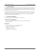


Table Of Contents
- Trademarks
- About this Manual
- Federal Communications Commission Radio Frequency Interference Statement
- Warranty and Customer Service
- Customer Service, Product Support Information, and Training
- 4205 System Description
- Microwave Path Engineering Basics
- Engineering Guidelines
- Network Turnup Procedure
- User Interface Guide
- Troubleshooting Guide

TRACER 4205 System Manual Section 2, Microwave Path Engineering Basics
612804205L1-1A © 2002 ADTRAN, Inc. 19
Antenna Beam Patterns
Directly related to the subject of antenna alignment is the topic of antenna beam patterns. Antennas being
used with the TRACER 4205 system will have a particular beam shape determined in part by the physical
construction and geometry of the antenna. The antenna beam patterns are characterized by a dominant
main lobe, which is the preferred lobe to use for point-to-point communications, and several side lobes, as
shown in Figure 2 on page 19. The antenna alignment step to setting up a microwave link is in fact steering
the main lobes of both antennas until the main lobe of one transmitter is centered on the receiving element
of the receiving antenna.
Figure 2. Typical Antenna Beam Pattern
Antennas are also designed to radiate RF energy efficiently for a specific range of frequencies. Please
consult the data sheet for your particular antenna make and model to ensure that it is specified to operate in
the 5725 MHz to 5850 MHz frequency band.
Fresnel Zones, Earth Curvature, & Antenna Heights
The Fresnel zones correspond to regions in the microwave path where reflections of the intended signal
occur and combine in both constructive and destructive manners with the main signal, thereby either
enhancing or reducing the net power at the receiver.
In general, the odd numbered Fresnel zones (1, 3, 5, ...) add constructively at the receiver, while the even
numbered Fresnel zones (2, 4, 6, ...) add destructively at the receiver.
The first Fresnel zone corresponds to the main lobe, and must be at least 60% free of physical obstructions for
the path calculations to be valid. Since the main lobe contains the vast majority of the microwave energy, this
zone is typically used to determine proper antenna heights when placing antennas on towers or buildings.
The curvature of the Earth becomes a legitimate obstruction for path lengths of 7 miles or greater, and must
also be accounted for when determining minimum antenna heights.
The aggregate expression for minimum antenna height that incorporates both the 60% first Fresnel zone
and the Earth curvature is given by
where f is in GHz and d is in miles.
main lobe
side lobes
h 72.1
d
4f
----- 0.125d
2
+= (feet)