
User guide

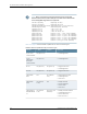


Table 4: Loopback Modes by Interface Type (continued)
Usage GuidelinesLoopback ModesInterface
Configuring Serial Loopback CapabilityDCE local, DCE
remote, local, and
remote
Serial (EIA-530)
Configuring SONET/SDH Loopback CapabilityLocal and remoteSONET/SDH
Configuring T1 Loopback Capability and
Configuring T3 Loopback Capability
See also Configuring the T1 Remote Loopback
Response
Local, payload, and
remote
T1 and T3
To configure loopback testing, include the loopback statement:
loopback mode;
You can include this statement at the following hierarchy levels:
•
[edit interfaces interface-name aggregated-ether-options]
•
[edit interfaces interface-name ds0-options]
•
[edit interfaces interface-name e1-options]
•
[edit interfaces interface-name e3-options]
•
[edit interfaces interface-name fastether-options]
•
[edit interfaces interface-name gigether-options]
•
[edit interfaces interface-name serial-options]
•
[edit interfaces interface-name sonet-options]
•
[edit interfaces interface-name t1-options]
•
[edit interfaces interface-name t3-options]
Interface Diagnostics
BERT allows you to troubleshoot problems by checking the quality of links. You can
configure any of the following interfaces to execute a BERT when the interface receives
a request to run this test: E1, E3, T1, T3; the channelized DS3, OC3, OC12, and STM1
interfaces; and the channelized DS3 IQ, E1 IQ, and OC12 IQ interfaces.
A BERT test requires a line loop to be in place on either the transmission devices or the
far-end router. The local router generates a known bit pattern and sends it out the transmit
path. The received pattern is then verified against the sent pattern. The higher the bit
error rate of the received pattern, the worse the noise is on the physical circuit. As you
move the position of the line loop increasingly downstream toward the far-end router,
you can isolate the troubled portion of the link.
87Copyright © 2014, Juniper Networks, Inc.
Chapter 6: Interface Diagnostics