
Installation guide


Total Access 900e Series Hardware Installation Guide Appendix A
64243916F1-34A Copyright © 2013 ADTRAN, Inc. 33
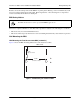
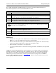
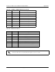
Table A-5. 1000Base-T Gigabit Ethernet Port Pinouts
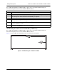
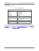
Table A-6. CRAFT Port Pinouts
Pin Name Description
1 TRD0+ Transmit/Receive Positive
2 TRD0- Transmit/Receive Negative
3 TRD1+ Transmit/Receive Positive
4 TRD2+ Transmit/Receive Positive
5 TRD2- Transmit/Receive Negative
6 TRD1- Transmit/Receive Negative
7 TRD3+ Transmit/Receive Positive
8 TRD3- Transmit/Receive Negative
Pin Name Description
1 DCD Data Carrier Detect (output)
2 RD Receive Data (output)
3 TD Transmit Data (input)
4 DTR Data Terminal Ready (input)
5 GND Ground - connected to unit chassis
6 DSR Data Set Ready (output)
7 RTS Request To Send - flow control (input)
8 CTS Clear To Send - flow control (output)
9 — Not Connected
Connection directly to an external modem requires a cross-over cable.