
Installation guide


Physical Description Total Access 900e Series Hardware Installation Guide
16 Copyright © 2010 ADTRAN, Inc. 64243916F1-34A
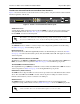
10/100Base-T Ethernet Interfaces and LEDs
The Ethernet ports (ETH 0/1 and ETH 0/2) are RJ-48 connectors. The status LEDs, labeled ETH 1 and
ETH 2, are located on the front panel.See Table A-4 on page 32 for the Ethernet port pinouts.
10/100/1000Base-T Ethernet Interface
The Gigabit Ethernet port (GIG 0/1) is an RJ-48C connector. That status LED, labeled GIG 1 is located
on the front panel. See Table A-5 on page 33 for the Gigabit Ethernet port pinouts.
USB Interface (Future Release)
The USB interface is Type A USB host connector and is provided for use with 3G/4G modems or flash
drives. The status LED, labeled
USB, is located on the front panel. A USB power switch is used to
limit the current drawn by a device connected to the USB port.
CRAFT Interface
The CRAFT interface is an EIA-232 serial port (DCE) that provides for local management and
configuration (using a DB-9 female connector). Table A-6 on page 33 shows the
CRAFT port pinouts.
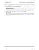
Grounding Point
A grounding point is provided to connect the unit to a protective earth ground. Refer to Supplying
Power to the Unit on page 25 for connection details.
Battery Backup Connection
An optional battery backup unit (P/N 1200641L1) is available for use in case of power outages. The
battery backup unit connects to the
BBU port, which also charges the unit during operation. Refer to
the documentation available for your specific battery backup unit for more information on this
connection, or refer to Battery Backup Unit on page 26 for a more details.
Power Connection
The rear panel has a power input to a 120 VAC power supply with an IEC connector. The appropriate
three-prong cable is included in the shipment. Refer to Supplying Power to the Unit on page 25 for
connection details.
Connection directly to an external modem requires a cross-over cable.