
Installation guide


Total Access 900e Series Hardware Installation Guide Physical Description
64243916F1-34A Copyright © 2010 ADTRAN, Inc. 15
Reviewing the Front Panel Design
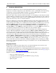
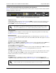
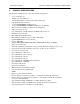
Figure 1 shows the Total Access 900e Series front panel.
Figure 1. Total Access 900e Series Front Panel Layout
Front Panel Features
Status LEDs
The status LEDs are located on the left side of the front panel. The VOICE LED indicates the status of
the voice ports. The
STATUS LED indicates the unit’s status. The GIG 1 LED indicates the status of
the Gigabit Ethernet port. The
USB LED indicates the status of the USB port. The T1 1 through 4
LEDs reflect the status of the network interfaces. The ETH 1 and ETH 2 LEDs reflect the status of the
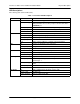
LANs. Table 1 on page 19 below describes the front panel LEDs.
Reviewing the Rear Panel Design
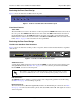
Total Access 908e Rear Panel Interfaces
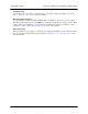
Figure 2 shows the Total Access 908e product’s rear panel, which contains identical interfaces regardless
of the model.
Figure 2. Total Access 908e Rear Panel Layout
VOICE Connection
A single 50-pin female amphenol connector, labeled VOICE, provides the interconnect wiring for the
analog FXS/FXO circuits. See Table A-1 on page 33 for voice connector pinouts. The status LED,
labeled
VOICE, is located on the front panel.
FXO 0/0 Interface
The FXO 0/0 interface is an RJ-11 connector and provides a single analog trunk for local call routing.
See Table A-2 on page 32 for the FXO port pinouts.
Network Interfaces
The network interfaces (T1 0/1 through T1 0/4) interfaces are DS1 RJ-48C pin connections. See Table
A-3 on page 32 for the network interface pinouts. The status LEDs, labeled
T1 1 through 4, are located
on the front panel.
The number of circuits used (1 through 24) is dependent on the Total Access 900e
Series model. FXO interfaces use circuits 17 through 24 depending on the model.
Total Access 900e
STATUS
VOICE
GIG 1
USB
1
T1
2
3
4
ETH 1
ETH 2
CRAFT
BBU
GIG 0/1
10/100/1000
BASE-T
T1 0/1
FXO
0/0
VOICE
T1 0/3
ETH 0/2
AC INPUT
ETH 0/1
T1 0/2 T1 0/4
USB