
Technical data


90362-01 NetBlazer LS Installation 2-3
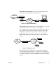
NetBlazer Front Views
Figure 2-3 shows the front panels for both the ISDN and Dual DTE models
of the NetBlazer LS. Both models feature a rocker-type power switch on the
left side of the front panel.
Figure 2-3. NetBlazer LS Front LED Panels
Both NetBlazer models show PWR (Power) and RDY (Ready) status indica-
tors by the power switch. The
PWR LED is on when AC power is applied to
the NetBlazer. The
RDY LED is on when the NetBlazer has completed boot-
ing up.
Note:
The pinhole to the right of the power switch is used to reset your NetBlazer
to the factory defaults by erasing all saved configuration files. To reset the
NetBlazer, turn the NetBlazer’s power off and insert one end of a straight-
ened paper clip into the pinhole. Holding the paper clip firmly pushed in,
turn the NetBlazer back on and continue to press in on the paper clip for five
or more seconds. When you release the paper clip, the NetBlazer will boot
up using factory default settings.
ISDN
Dual DTE
NetBlazer
LS ISDN
POWER PWR RDY ETHERNET LOCALTALK DTE BRI
TRANS
RECV
COL
UTP/BNC
TRAN
RECV
CD
SD
RD
D
B1
B2
NetBlazer
LS 2-PT
POWER PWR RDY ETHERNET LOCALTALK DTE A DTE B
TRANS
RECV
COL
UTP/BNC
TRAN
RECV
CD
SD
RD
CD
SD
RD