
Installation guide


NetVanta 4305 Hardware Installation Guide Appendix A. Connector Pin Definitions
61200890L1-34B © 2004 ADTRAN, Inc. 49
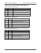
Dial Backup (DBU) Connectors
Table A-9 describes the pinouts for the following modules: 56/64K, T1/FT1 (1st generation), and T1/
FT1+DSX-1 (1st generation).
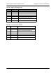
Table A-10 describes the pinouts for the following modules: Serial, E1/FE1, E1/FE1 with G.703 Drop, T1/
FT1 (2nd generation), Dual T1 NIM, and T1/FT1+DSX-1 (2nd generation).
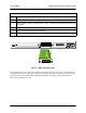
Table A-9. DBU Connector Pinouts
Pin Name Description
1 R1 Network–Ring 1
2 T1 Network—Tip 1
3 — Unused
4T Network–Tip
5 R Network–Ring
6-8 — Unused
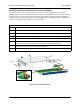
Table A-10. DBU Connector Pinouts
Pin Name Description
1-2 — Unused
3 R1 Network–Ring 1
4 R Network–Ring
5T Network—Tip
6 T1 Network—Tip 1
7-8 — Unused
An optional DIM is required for dial backup applications.