NETVANTA 3000 SERIES ROUTERS Hardware Installation Guide 1202860L1 NetVanta 3200 Unit 1200870L1 NetVanta 3205 Unit (AC Version) 1200980L1 NetVanta 3205 Unit (DC Version) 1200880L1 NetVanta 3305 Unit 1200861L1 NetVanta 56K/64K Network Interface Module 1200862L1 NetVanta T1/FT1 Network Interface Module 1200863L1 NetVanta T1/FT1+DSX-1 Network Interface Module 1200866L1 NetVanta Serial Network Interface Module 1200867L1 NetVanta SHDSL Network Interface Module 1200864L1 NetVanta Analog Modem
Hardware Installation Guide NetVanta 3000 Series Routers Trademarks Any brand names and product names included in this manual are trademarks, registered trademarks, or trade names of their respective holders. To the Holder of this Manual The contents of this manual are current as of the date of publication. ADTRAN reserves the right to change the contents without prior notice.
NetVanta 3000 Series Routers Hardware Installation Guide Conventions Notes provide additional useful information. Cautions signify information that could prevent service interruption. Warnings provide information that could prevent damage to the equipment or endangerment to human life. Safety Instructions When using your communications equipment, please follow these basic safety precautions to reduce the risk of fire, electrical shock, or personal injury: 1.
Hardware Installation Guide NetVanta 3000 Series Routers FCC regulations require that the following information be provided in this manual: 1. This equipment complies with Part 68 of FCC rules and requirements adopted by ACTA. Each of the Network Interface Modules and the Dial Backup Interface Modules has a label showing the FCC registration number and ringer equivalence number (REN). If requested, provide this information to the telephone company. 2.
NetVanta 3000 Series Routers Hardware Installation Guide FCC Radio Frequency Interference Statement This equipment has been tested and found to comply with the limits for a Class A digital device, pursuant to Part 15 of the FCC Rules. These limits are designed to provide reasonable protection against harmful interference when the equipment is operated in a commercial environment.
Hardware Installation Guide NetVanta 3000 Series Routers Industry Canada Compliance Information Notice: The Industry Canada label applied to the product (identified by the Industry Canada logo or the “IC:” in front of the certification/registration number) signifies that the Industry Canada technical specifications were met. Notice: The Ringer Equivalence Number (REN) for this terminal equipment is supplied in the documentation or on the product labeling/markings.
NetVanta 3000 Series Routers Hardware Installation Guide Affidavit for Connection Of Customer Premises Equipment to 1.
Hardware Installation Guide NetVanta 3000 Series Routers Warranty and Customer Service ADTRAN will replace or repair this product within the warranty period if it does not meet its published specifications or fails while in service. Warranty information can be found at: http://support.adtran.com (Click on Warranty and Repair Information, under Support.) Product Registration Registering your product helps ensure complete customer satisfaction.
NetVanta 3000 Series Routers Hardware Installation Guide Pre-Sales Inquiries and Applications Support Your reseller should serve as the first point of contact for support. If additional pre-sales support is needed, the ADTRAN Support web site provides a variety of support services such as a searchable knowledge base, latest product documentation, application briefs, case studies, and a link to submit a question to an Applications Engineer. All of this, and more, is available at: http://support.adtran.
Hardware Installation Guide NetVanta 3000 Series Routers Training The Enterprise Network (EN) Technical Training Department offers training on our most popular products. These courses include overviews on product features and functions while covering applications of ADTRAN's product lines. ADTRAN provides a variety of training options, including customized training and courses taught at our facilities or at your site.
HARDWARE INSTALLATION GUIDE Contents Introduction to the NetVanta Solution . . . . . . . . . . . . . . . . . . . . . . . . . . . . . . . . . . . . . . . . . . . . . . Features and Specifications . . . . . . . . . . . . . . . . . . . . . . . . . . . . . . . . . . . . . . . . . . . . . . . . . Unpack and Inspect the System . . . . . . . . . . . . . . . . . . . . . . . . . . . . . . . . . . . . . . . . . . . . . . . . . Contents of ADTRAN Shipments . . . . . . . . . . . . . . . . . . . . . . . . . . . . . . .
Hardware Installation Guide NetVanta 3000 Series Routers FIGURES Figure 1. Figure 2. Figure 3. Figure 4. Figure 5. Figure 6. Figure 7. Figure 8. Figure 9. Figure 10. Figure 11. Figure 12. Figure 13. Figure 14. Figure 15. Figure 16. Figure 17. Figure 18. Figure 19. Figure 20. NetVanta 3200 Front Panel Layout . . . . . . . . . . . . . . . . . . . . . . . . . . . . . . . . . . . . . . . . NetVanta 3205 Front Panel Layout . . . . . . . . . . . . . . . . . . . . . . . . . . . . . . . . . . . . . . . .
NetVanta 3000 Series Routers 1. Hardware Installation Guide INTRODUCTION TO THE NETVANTA SOLUTION The NetVanta 3000 Series is a line of modular access routers designed for cost-effective branch office connectivity over frame relay or point-to-point (PPP) networks. These modular platforms offer a complete solution for access routing and WAN connectivity in a single, compact package. The Netvanta 3000 Series includes the NetVanta 3200, NetVanta 3205 (AC or DC powered), and NetVanta 3305.
Hardware Installation Guide • • • • NetVanta 3000 Series Routers NetVanta 3200: 9.3”W x 2.1”H x 6.1”D NetVanta 3205 and NetVanta 3305: 17.25” x 1.26”H x 7.75”D AC power requirements: 6 W max, 60mA (regardless of configuration) DC power requirements: 6 W max; +21 to +28.3 VDC (+24 VDC nominal); -40.5 to -64 VDC (-48 VDC nominal) This hardware installation guide describes the NetVanta 3000 Series units, details basic functionality, gives installation instructions, and lists unit specifications.
NetVanta 3000 Series Routers Hardware Installation Guide NetVanta 3205 (DC version) Shipments of the NetVanta 3205 (DC) include the following items: • • • NetVanta 3205 (DC version) base unit with attached mounting ears ADTRAN OS System Documentation CD Warranty Card NetVanta 56K/64K NIM Shipments of the 56K/64K NIM include the following items: • • • 56K/64K Network Interface Module Quick Start Guide 6-foot RJ-45 to RJ-45 cable (ADTRAN P/N 3127004) NetVanta T1/FT1 NIM (1200862L1) Shipments of the T
Hardware Installation Guide NetVanta 3000 Series Routers NetVanta Analog Modem DIM (1200864L1) Shipments of the Analog Modem DIM include the following items: • • • Analog Modem Dial Backup Interface Module Quick Start Guide RJ-45 to RJ-11 cable (ADTRAN P/N 3125M007@A) NetVanta ISDN BRI DIM (1200865L1) Shipments of the ISDN BRI DIM include the following items: • • • ISDN BRI Dial Backup Interface Module Quick Start Guide RJ-45 to RJ-11 cable (ADTRAN P/N 3125M007@A) NetVanta VPN Accelerator Card (1202
NetVanta 3000 Series Routers 2. Hardware Installation Guide PRODUCT OVERVIEW Reviewing the Base Unit Front Panel Designs Figure 1 shows the NetVanta 3200 front panel. Figure 1. NetVanta 3200 Front Panel Layout Figure 2 shows the NetVanta 3205 front panel. Figure 2. NetVanta 3205 Front Panel Layout Figure 3 shows the NetVanta 3305 front panel. Figure 3. NetVanta 3305 Front Panel Layout 61200860L1-34C © 2003 ADTRAN, Inc.
Hardware Installation Guide NetVanta 3000 Series Routers Front Panel LEDs Table 1 describes the front panel LEDs. Table 1. NetVanta 3000 Series Routers LEDs For these LEDs… This activity… Indicates that… STATUS Green (blinking) The unit is powering up. On power-up the STAT LED blinks rapidly for five seconds, during which time the user may escape to boot mode from the console port. Green (solid) The power is on and self-test passed.
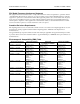
NetVanta 3000 Series Routers Hardware Installation Guide Reviewing the Base Unit Rear Panel Designs Figure 4 through Figure 7 show the rear panels for the NetVanta 3000 Series Routers. Each chassis is shown with the T1/FT1+DSX-1 NIM installed. The Activity and Link LEDs, which are present on all NetVanta Ethernet ports, are pointed out in Figure 4. Link LED Activity LED WAN-T1 DSX-1 DBU ETH 0/1 12V CONSOLE NOTE: OPTIONAL MODULE REQUIRED FOR DBU. POWER SLOT 1 NET/DBU Figure 4.
Hardware Installation Guide NetVanta 3000 Series Routers Rear Panel Interfaces and LEDs 10/100BaseT Ethernet Interface and Activity LEDs The Ethernet port is an RJ-48C connector with LEDs. The yellow activity LED flashes when data traffic is being sent or received on the Ethernet port. The green link LED is on when the router has a good connection to the LAN. See Table A on page 47 for the Ethernet port pinout.
NetVanta 3000 Series Routers 3. Hardware Installation Guide OPTION MODULES The NetVanta 3000 Series offers several option modules designed to meet a variety of networking requirements. The option modules are of two types: plug-in Network Interface Modules (NIMs) and plug-on Dial Backup Interface Modules (DIMs). NIMs are cards which plug directly into the option module slot (labeled SLOT x NET/DBU), located on the rear of the base unit.
Hardware Installation Guide NetVanta 3000 Series Routers Network Interface Modules NetVanta 56K/64K NIM (P/N 1200861L1) The 56K/64K NIM (shown in Figure 8) provides a WAN interface for the NetVanta 3000 Series Routers. This module provides a single 56K or 64K DDS network interface. Refer to Table E on page 49 for the WAN-DDS connector pinout, and Table L on page 51 for the DBU connector pinout. An optional DIM is required for dial backup applications. Figure 8.
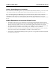
NetVanta 3000 Series Routers Hardware Installation Guide NetVanta T1/FT1 NIM (P/N 1200862L1) The T1/FT1 NIM (shown in Figure 9) provides a T1 WAN interface for the NetVanta 3000 Series Routers. This provides a full T1 or fractional T1 network interface. Refer to Table F on page 49 for the WAN-T1 connector pinout, and Table L on page 51 for the DBU connector pinout. An optional DIM is required for dial backup applications. WAN-T1 DBU Figure 9.
Hardware Installation Guide NetVanta 3000 Series Routers Environmental • • • Operating Temperature: Storage Temperature: Relative Humidity: 0 to 50 oC -40 to 85 oC Up to 95% noncondensing Physical • 24 Dimensions: 4.25" x 2.75" © 2003 ADTRAN, Inc.
NetVanta 3000 Series Routers Hardware Installation Guide NetVanta T1/FT1+DSX-1 NIM (P/N 1200863L1) The T1/FT1 + DSX-1 NIM (shown in Figure 10) provides a T1 WAN interface for the NetVanta 3000 Series Routers. The T1/FT1 + DSX-1 NIM provides a full T1 or fractional T1 network interface and a DSX-1 interface. Refer to Table F on page 49 for the WAN-T1 connector pinout, Table H on page 50 for the DSX-1 connector pinout, and Table L on page 51 for the DBU connector pinout.
Hardware Installation Guide NetVanta 3000 Series Routers Diagnostics • • • • Test pattern generation and detection: QRSS and 511 Network loopbacks (local and remote); responds to both INBAND and FDL loop codes (T1 interface only) Alarm generation and detection Network and user sets of performance data (15 minute and 24 hour) Relevant Requirements/Standards • • • • • • • EMC - see Electromagnetic Compatibility (EMC) Table on page 5.
NetVanta 3000 Series Routers Hardware Installation Guide NetVanta Serial NIM (P/N 1200866L1) The NetVanta Serial NIM (shown in Figure 11) is user-configurable to be either a V.35 or X.21 (V.11) interface. This module supports rates up to a maximum of 10 Mbps. An additional V.35 (ADTRAN P/N 1200873L1) or X.21 (ADTRAN P/N 1200874L1) cable is required (see Caution, below). Refer to Table K on page 51 for the SERIAL connector pinout, and Table L on page 51 for the DBU connector pinout.
Hardware Installation Guide NetVanta 3000 Series Routers Environmental • • • Operating Temperature: Storage Temperature: Relative Humidity: 0 to 50 oC -40 to 85 oC Up to 95% noncondensing Physical • 28 Dimensions: 4.25" x 2.75" © 2003 ADTRAN, Inc.
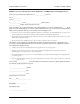
NetVanta 3000 Series Routers Hardware Installation Guide NetVanta SHDSL NIM (P/N 1200867L1) The NetVanta SHDSL NIM (shown in Figure 12) provides a WAN SHDSL interface for the NetVanta. Refer to Table J on page 50 for the SHDSL connector pinout. The DBU connector on this module is reserved for future enhancements. WAN-SHDSL DBU Figure 12.
Hardware Installation Guide NetVanta 3000 Series Routers NetVanta E1/FE1 NIM (P/N 1200868L1) The NetVanta E1 module (see Figure 13) provides a WAN/E1 interface for the NetVanta 3000 Series Routers meeting the requirements of ITU-T G.703/G.704. The module provides a single 2.048 Mbps network interface. Refer to Table G on page 49 for the pinouts. WAN-E1 DBU Figure 13.
NetVanta 3000 Series Routers Hardware Installation Guide NetVanta E1/FE1 with G.703 Drop NIM (P/N 1200878L1) The NetVanta E1/FE1 with G.703 Drop module (see Figure 14) provides a single WAN/E1 interface (2.043 Mbps) with user-selectable TS0 assignment and a G.703 drop port which may be used to drop and insert traffic to an E1 PBX. Refer to Table I on page 50 for the pinouts. WAN-E1 G.703 DBU Figure 14. NetVanta E1/FE1 with G.
Hardware Installation Guide NetVanta 3000 Series Routers Relevant Requirements/Standards • • • • • ACIF S016 ACA TS001 ETSI TBR 12 / TBR 13 EMC - see Electromagnetic Compatibility (EMC) Table on page 5. ITU G.703, ITU-T G.704 (CRC-4), ITU-T G.823, ITU-T G.797 Environmental • Operating temperature: 0 °C to 50 °C Physical • 32 Dimensions: 4.25” x 2.75” © 2003 ADTRAN, Inc.
NetVanta 3000 Series Routers Hardware Installation Guide Dial Backup Interface Modules NetVanta Analog Modem DIM (P/N 1200864L1) The Analog Modem DIM provides a modem with data rates up to 33.6 kbps for the NetVanta 3000 Series Routers. This DIM is a plug-on card that connects to the NIM. For installation instructions, see Installing Dial Backup and Network Interface Modules on page 41. Features and Specifications Features • • ITU V.
Hardware Installation Guide NetVanta 3000 Series Routers NetVanta ISDN BRI DIM (P/N 1200865L1) The NetVanta ISDN BRI DIM provides dial backup access to the public switched telephone network (PSTN) via Basic Rate ISDN for the NetVanta 3000 Series Routers. This DIM is a plug-on module that connects to the NIM.
NetVanta 3000 Series Routers 4. Hardware Installation Guide UNIT INSTALLATION The instructions and guidelines provided in this section cover hardware installation topics such as wallmounting/rackmounting the unit and installing option cards.
Hardware Installation Guide NetVanta 3000 Series Routers Mounting Options If you have purchased the VPN Accelerator Card, install it first (see Installing the NetVanta VPN Accelerator Card (1202368L1) on page 43). The NetVanta 3200 may be installed in a wallmount or tabletop configuration. The NetVanta 3205 and NetVanta 3305 may be installed in a tabletop, wallmount, or 19-inch rackmount configuration.The following sections provide step-by-step instructions for rackmounting and wallmounting.
NetVanta 3000 Series Routers Hardware Installation Guide Wallmounting NetVanta 3000 Series Routers NetVanta 3200 Instructions for Wallmounting NetVanta 3200 Step Action 1. Decide on a location for the NetVanta 3200. Keep in mind that the unit needs to be mounted at or below eye-level so that the LEDs are viewable. 2. Prepare the mounting surface by attaching a board (typically plywood, 3/ 4" to 1" thick) to a wall stud. Important! Mounting to a stud ensures stability.
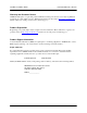
Hardware Installation Guide NetVanta 3000 Series Routers NetVanta 3205 and NetVanta 3305 Instructions for Wallmounting NetVanta 3205/NetVanta 3305 Step Action 1. Remove the mounting ears. Rotate them 90o so that the portion of the bracket with the mounting holes is flush with the bottom of the chassis, and reattach them to the chassis (see Figure 16). 2. Decide on a location for the NetVanta 3205/NetVanta 3305.
NetVanta 3000 Series Routers Hardware Installation Guide Figure 17. Wallmounting the NetVanta 3205/NetVanta 3305 61200860L1-34C © 2003 ADTRAN, Inc.
Hardware Installation Guide NetVanta 3000 Series Routers Supplying Power to the Unit As shipped, each NetVanta 3000 Series Router is set to factory default conditions. After installing the base unit and any option modules, the NetVanta 3000 Series Router is ready for power-up. To power-up the unit, ensure that the unit is properly connected to an appropriate power source (as outlined in the sections which follow).
NetVanta 3000 Series Routers Hardware Installation Guide Installing Dial Backup and Network Interface Modules The DIMs plug on to the NIMs. The NIMs are then installed in the rear panel option module slot. The following tables list the installation steps. Also see Figure 19 on page 42. Always remove power from the unit prior to removing or installing a module. Improper installation may result in damage to the modules. Instructions for Installing the DIMs Step Action 1. Remove power from the unit.
Hardware Installation Guide NetVanta 3000 Series Routers Instructions for Installing the NIMs Step Action 1. Remove power from the unit. 2. Slide the option module into the option slot until the module is firmly seated against the front of the chassis. 3. Secure the pins at both edges of the module. 4. Connect the cables to the associated device(s). 5. Restore power to the unit. ETH 0/1 CONSOLE POWER SLOT 1 NET/DBU WAN-T1 DSX-1 WAN-DDS 12V DBU Figure 19.
NetVanta 3000 Series Routers Hardware Installation Guide Installing the NetVanta VPN Accelerator Card (1202368L1) The optional VPN Accelerator Card plugs into a 32-bit PCI slot and is designed to be used in the NetVanta 3305 and following products to provide encryption/decryption and security acceleration services for the host processor. The card is a 1-U high PC card with gold fingers to interface to a 3.3V keyed PCI connector.
Hardware Installation Guide 44 NetVanta 3000 Series Routers © 2003 ADTRAN, Inc.
APPENDIX A. PIN ASSIGNMENTS The following tables provide the pin assignments for the base units, network interface modules (NIMs), and dial backup interface modules (DIMs). Base Unit Pinouts Table A. 10/100BaseT Ethernet Port Pinouts Pin Name Description 1 TX1 Transmit Positive 2 TX2 Transmit Negative 3 RX1 Receive Positive 4,5 — UNUSED 6 RX2 Receive Negative 7,8 — UNUSED Table B.
Hardware Installation Guide NetVanta 3000 Series Routers Table C.
NetVanta 3000 Series Routers Hardware Installation Guide NIM Pinouts WAN Connectors Table E. WAN-DDS Connector Pinouts Pin Name Description 1 R1 Transmit data to the network–RING 1 2 T1 Transmit data to the network–TIP 1 3-6 — UNUSED 7 T Receive data from the network–TIP 8 R Receive data from the network–RING Table F.
Hardware Installation Guide NetVanta 3000 Series Routers Table H. DSX-1 Connector Pinouts Pin Name Description 1 R Transmit data toward the DTE–RING 2 T Transmit data toward the DTE–TIP 3 — UNUSED 4 R1 Receive data from the DTE–RING 1 5 T1 Receive data from the DTE–TIP 1 6-8 — UNUSED Table I. G.
NetVanta 3000 Series Routers Hardware Installation Guide Table K. Serial NIM Connector Pinouts Pin Name Pin Name 1 TD_A 14 TD_B 2 ETC_A 15 ETC_B 3 TCLK_A 16 TCLK_B 4 RCLK_A 17 RCLK_B 5 RD_A 18 RD_B 6 DCD_A 19 UNUSED 7 DTR_A 20 UNUSED 8 RTS_A 21 UNUSED 9 RTS_B (V.11 only) 22 UNUSED 10 CTS_B (V.11 only) 23 UNUSED 11 CTS_A 24 UNUSED 12 DSR_A 25 UNUSED 13 TM_A 26 GROUND DBU Connectors Table L.
Hardware Installation Guide 52 NetVanta 3000 Series Routers © 2003 ADTRAN, Inc.
Index NUMERICS L 10/100BaseT Ethernet 14 interface 21, 47 pinout 47 56K/64K Interface 14 LAN TD/RD LED 19 LEDs 14, 19 LNK LED 19 M A accelerator card 45 mounting options rack 38 wall 39 B Bridging 14 C CLI 14 Console Port 21 pinout 47, 48 Contents of Shipment 15 D DBU Interface pinout 51 DBU LED 19 Dial Backup 14 Dial Backup Interface Modules (DIMs) NetVanta Analog Modem DIM 35 features and specifications 35 shipping contents 17 NetVanta ISDN BRI DIM 36 features and specifications 36 shipping conten
Hardware Installation Guide NetVanta T1/FT1 NIM 24 features and specifications 24 shipping contents 16 NetVanta T1/FT1+DSX-1 NIM 26 features and specifications 26 shipping contents 16 N-Formant 14 NIM installation 43 NIMs 22 NetVanta 56K/64K NIM 23 features and specifications 23 shipping contents 16 NetVanta E1/FE1 NIM shipping contents 16 NetVanta E1/FT1+ G.