
Unit installation

4 Issue 1, November 2003 61223026L2-5A
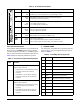
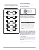
Front Panel Pushbuttons
Two loopback (LBK) pushbuttons are accessible from
the front panel. The
REM loopback button controls a
customer loopback at the H2TU-C. The
LOC loopback
button controls a bidirectional loopback at the H2TU-R.
Table 5 details the loopback pushbutton operation.
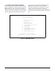
3. CONNECTIONS
All connections of the H2TU-R are made through card
edge connectors. The pin assignments for this unit are
shown in Tabl e 6.
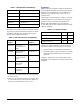
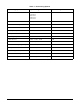
Table 4. Front Panel Indications
Name Indication Description
DSL Green
Red
DSL sync, no errors currently detected, and signal margin > 2 dB
No DSL sync, errors being detected, or signal margin ≤ 2 dB
DS1 Green
Red
DS1 signal is present and no errors currently being detected
No DS1 signal or framing mismatch
ALM OFF
Red
Yellow
No active alarm present
Loss of DS1 signal to the unit
Loss of DSX signal to the H2TU-C
ESF/SF OFF
Yellow
Green
Unit is provisioned for UNFRAMED data
Unit is provisioned for ESF data
Unit is provisioned for SF data
B8ZS/
AMI
Yellow
Green
Indicates DS1 is provisioned for B8ZS line code
Indicates DS1 is provisioned for AMI line code
LLB/
RLB
OFF
Yellow
Green
Unit is NOT in loopback
Unit is in loopback (network and/or customer) at H2TU-R
Active remote loopback from the H2TU-C toward the customer
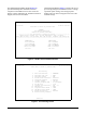
TX
RX
REM
LOC
L
B
K
1223026L2
DSL
DS1
ALM
(GRN)
SF
(YEL)
ESF/
(GRN)
AMI
(YEL)
(GRN)
(YEL)
B8ZS
/
LLB/ RLB
C
U
S
T
M
O
N
R
S
2
3
2
U
R
H T
Table 5. Front Panel Loopback Pushbuttons
Switch
Label Function
REM Pressing this button changes the H2TU-C
loopback state as follows:
• If the H2TU-C is not in loopback, pressing
this button will activate a bilateral
loopback.
• If the H2TU-C is in loopback, pressing
this button will deactivate the bilateral
loopback.
LOC Pressing this button changes the H2TU-R
loopback state as follows:
• If the H2TU-R is not in loopback, pressing
this button will activate a bilateral
loopback.
• If the H2TU-R is in loopback, pressing
this button will deactivate the bilateral
loopback
Table 6. Card Edge Pin Assignments
Pin Name Description
1 CH GND Chassis ground
5 DS1-T1 DS1 receive out tip (to customer)
7 H1-T HDSL2 Loop tip (facility)
11 CH GND Chassis ground
12 GND Ground for protection switching
13 H1-R HDSL2 Loop ring (facility)
15 DS1-R1 DS1 receive out ring (to customer)
20 VCC +5 VDC for protection switching
27 CH GND Chassis ground
40 PROT-1 Control line for protection switching
49 DS1-R DS1 transmit in ring (from customer)
55 DS1-T DS1 transmit in tip (from customer)