
Product specifications

61181113L2-5A Issue 1, November 2003 3
This device complies with Part 15 of the FCC rules.
Operation is subject to the following two conditions:
1. This device may not cause harmful interference.
2. This device must accept any interference received,
including interference that may cause undesired
operation.
WARNING
Up to –200 VDC may be present on telecom-
munications wiring. The DSX-1 interface is
intended for connection to intra-building
wiring only. Ensure chassis ground is properly
connected.
NOTE
This product is intended for installation in
Restricted Access Locations only.
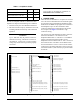
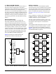
3. CONNECTIONS
The Total Access 3000 H2TU-C occupies one card slot
in a Total Access 3000 Shelf. Power and alarm signals
are provided to the card through the backplane of the
shelf. DSX1 and HDSL2 loop signals are connected to
the backplane on pins or mass termination shelf
connectors (amphenol) corresponding to the slot the
unit occupies. See Figure 3 for H2TU-C edge
connection wiring.
The Total Access 3000 shelf delivers DSX-1 from the
network to the H2TU-C via connectors on the
backplane labeled “Pair 7” and “Pair 8”. The HDSL2
signal is provided toward the customer via the
backplane connector labeled “Pair 2”. Pins 1 and 33 of
the connectors Pair 7 and Pair 8 are the DSX connec-
tions for the H2TU-C in Slot 1. Pins 2 and 34 of these
connectors are associated with Slot 2. Pins 3 and 35 are
associated with Slot 3, and so forth, up to pins 28 and 60
for Slot 28.
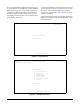
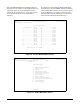
Figure 3. H2TU-C Edge Connector Wiring
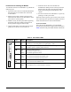
Table 2. Compliance Codes
Code Input Output
Power Code (PC) F C
Telecommunication Code (TC) – X
Installation Code (IC) A –
1
2
3
4
5
6
7
8
9
10
11
12
13
14
15
16
17
18
19
20
21
22
23
24
25
26
27
28
29
30
31
32
1
2
3
4
5
6
7
8
9
10
11
12
13
14
15
16
17
18
19
20
21
22
23
24
25
26
27
28
29
30
31
32
1
2
3
4
5
6
7
8
9
10
11
12
13
14
15
16
17
18
19
20
21
22
23
24
25
26
27
28
29
30
31
32
P
2, Row A P2, Row B P2, Row C
- 48 volt return
Interrupt Request
MUX B Receive Data
MUX A Receive Clock
MUX A Receive Data
Chassis ground
Chassis ground
SCU Control Lead
Fuse alarm
Interrupt Request Select
MUX B Transmit Clock
MUX A Transmit Clock
Test access bus Loop ring
Test access bus Loop tip
Receive DSX-1 Ring backup connection
Transmit DSX-1 Ring backup connection
Receive DSX-1 Ring normal connection
Transmit DSX-1 Ring normal connection
- 48 volt return
- 48 volt DC A
- 48 volt DC A
HDSL2 Loop Ring (facility)
HDSL2 Loop Tip (facility)
SCU Control Lead
SCU Control Lead
SCU Serial Interface
MUX B Transmit Data
MUX B Receive Clock
MUX A Transmit Data
Receive DSX-1 Tip backup connectio
n
Transmit DSX-1 Tip backup connectio
n
Receive DSX-1 Tip normal connection
Transmit DSX-1 Tip normal connectio
n
- 48 volt DC B
- 48 volt DC B