
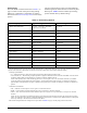
Product specifications

8 Issue 3, December 2003 61223006L1-5C
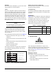
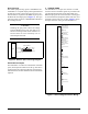
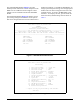
5. CONTROL PORT OPERATION
The H2TU-C provides a DB-9 connector on the front
panel that supplies an RS-232 interface for connection
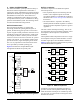
to a controlling terminal. The pinout of the DB-9 is
illustrated in Figure 7.
Figure 7. RS-232 (DB-9) Pin Assignments
The terminal interface operates at data rates from 1.2
kbps to 19.2 kbps. The asynchronous data format is
fixed at 8 data bits, no parity, and 1 stop bit. The line
wrap feature of emulation programs should also be
disabled.
The H2TU-C supports two types of terminal emulation
modes. The Manual Update Mode is a dumb terminal
mode, allowing easy access to print screen and log files
commands. This mode also includes a “3 SPACES TO
UPDATE” message on the top of the terminal screen
(press the spacebar 3 times to update the screen).
The Real Time Update Mode is a VT100 terminal
mode. This mode enables all screen highlighting and
cursor placement. Print screen and log file commands
are not available in this mode.
The default terminal mode is Real-Time Update.
NOTE
If you are using a personal computer (PC) with
terminal emulation capability, be sure to
disable any power saving programs.
Otherwise, communication between the PC
and the HDSL2 unit may be disrupted,
resulting in misplaced characters or screen
time outs.
The screens illustrated in Figure 8 through Figure 31
are for an HDSL2 circuit deployed with the ADTRAN
HDSL2 technology. The circuit includes an H2TU-C
and H2TU-R. Other configurations are possible (for
example, an HDSL2 repeater from another vendor’s
equipment), and their displays will vary slightly from
those shown in this section.
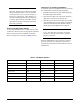
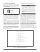
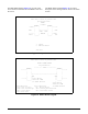
A terminal session is initiated by entering multiple
spacebar characters, which are used by the H2TU-C to
determine the speed of the terminal. Once the speed has
been determined, the ADTRAN HDSL2
Main Menu is
displayed from which the various OAM&P (Operation,
Administrative, Maintenance, and Provisioning)
screens may be accessed (Figure 8). To display a
particular screen from the menu, press the number key
associated with the screen title and then press the
ENTER
key.
Figure 8. ADTRAN HDSL2 Main Menu
6
7
8
9
1
2
3
4
5
TXD (Transmit Data
)
RXD (Receive Data
)
SGN (Signal Groun
d)
Circuit ID: 12/01/03 09:29:45
Adtran HDSL2 Main Menu
1. HDSL2 Unit Information
2. Provisioning
3. Span Status
4. Loopbacks and Test
5. Performance History
6. Scratch Pad, Ckt ID, Time/Date
7. Terminal Modes
8. Alarm History
9. Event History
10. System PM/Screen Report
11. Clear PM and Alarm Histories
12. Troubleshooting
13. Virtual Terminal Control
Selection: