
Product specifications

6 Issue 3, December 2003 61223006L1-5C
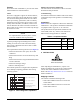
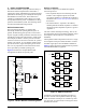
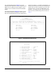
Span Powering
The default span powering option is ENABLED. The
T200 H2TU-C is capable of span powering the H2TU-R
by applying current to the local loop. From 10 to 150
mA of current is coupled onto the HDSL2 span to power
the H2TU-R when deployed (see Figure 3). The span
powering option can be set to DISABLED if the H2TU-
R is locally powered.
CAUTION
Disabling the span power removes all voltage
from the HDSL2 loop. This will result in an
absence of sealing current which could have an
adverse effect on circuit continuity over an
extended period of time.
Figure 3. H2TU-C Span Powering Diagram
H2TUC Alarm Outputs
The T200 H2TU-C contains an onboard fuse. If the fuse
opens, all front panel indicators will be off. This fuse is
not designed to be replaced in the field. A blown fuse
indicates that the card has malfunctioned and should be
replaced.
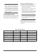
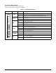
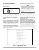
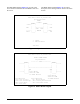
3. CONNECTIONS
The T200 H2TU-C occupies one card slot in a T200
enclosure. Power and alarm signals are provided to the
card through the backplane of the shelf. DSX1 and
HDSL2 loop signals are connected to the wirewrap pins
or mass termination (amphenol) shelf connectors corre-
sponding to the slot the unit occupies. Figure 4 shows
the edge connection wiring for the T200 H2TU-C.
Figure 4. H2TU-C Edge Connector Wiring
HDSL2
TIP (+)
RING (
-)
SPAN POWER
190V
SPAN CURRENT
1
2
3
4
5
6
7
8
9
10
11
12
13
14
15
16
17
18
19
20
21
22
23
24
25
26
27
28
29
30
31
32
33
34
35
36
37
38
39
40
41
42
43
44
45
46
47
48
49
50
51
52
53
54
55
Chassis Ground
Chassis Ground
DSX RX Tip
Chassis Ground
-48 VDC
DSX TX Ring
DSX TX Tip
HDSL2 Ring
-48 VR
DSX RX Ring
HDSL2 Tip