
Product specifications

61223006L1-5C Issue 3, December 2003 5
Provisioning
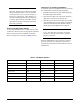
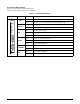
The T200 H2TU-C DIP switch shown on Table 3 on
page 3 controls several of the provisioning settings.
Otherwise, configuration is performed via software
discussed in the Control Port Operation section of this
practice.
The provisioning settings can be viewed and manipu-
lated through access to the firmware via the front panel
RS-232 port. Tab le 5 lists the available provisioning
options and their factory default settings.
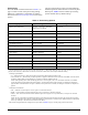
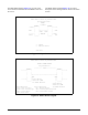
Table 5. Provisioning Options
Provisioning Option Option Settings Default Settings
1. DSX-1 Line Build Out * 0-133 ft., 133-266 ft., 266-399 ft.,
399-533 ft., 533-655 ft.
0 to 133 ft.
2. DSX-1/DS1 Line Code * B8ZS, AMI B8ZS
3. DSX-1/DS1 Framing SF, ESF, Unframed, Auto ESF
4. Force Frame Conversion
1
Disabled, Enabled Disabled
5. Smartjack Loopback Disabled, Enabled Enabled
6. Loopback Time Out * None, 120 Min 120 Minutes
7. Latching Loopback Mode
2 *
T1 (Disabled), FT1 (Enabled) T1 (Disabled)
8. DS1 Tx Level 0 dB, –7.5 dB, –15 dB –7.5 dB
9. Span Power * Enabled, Disabled Enabled
10. Customer Loss Indicator
3
AIS, Loopback, AIS/CI AIS/CI
11. Performance Reporting Messages None, SPRM, NPRM, AUTO (both) AUTO
12. Loop Attenuation Alarm Threshold 0 (Disabled), 1-99 dB 30 dB
13. SNR Margin Alarm Threshold 0 (Disabled), 1-15 dB 04 dB
14. Remote Provisioning Enabled, Disabled Enabled
1
The forced frame format conversion (FFFC) mode sets the H2TU-C to ESF and the H2TU-R to SF. This mode should be used to force
SF (DS1 from customer) to ESF (DSX-1 to network) conversion in the absence of network-provided ESF framing.
2
Latching Loopback Mode
• T1 — When optioned for T1 mode, the unit does not respond to DDS Latching Loopback codes.
• FT1 (Fractional T1) — DDS Latching Loopback operation is supported. The H2TU-C units which are in the HDSL circuit are treated
as Identical Tandem Data ports and the HTU-R is treated as a different Tandem Data port.
NOTE: When operating in FT1 mode and during periods of T1 loss of signal, LOS, or T1 AIS from the customer CI, the HDSL
system will send in the network direction from the HTU-C a Fractional DS1 idle signal consisting of a repeating 7E (HEX) byte
payload within a framed/unframed T1 signal. In addition, when optioned for FT1 mode, the setting for Customer Loss Response is
ignored.
3
Customer Loss Indicator
• AIS — Send AIS to network upon T1 loss of signal or T1 AIS from customer
• LPBK — HTU-R initiates a network loopback upon T1 loss of signal or T1 AIS from customer
• AIS/CI — HTU-R sends customer disconnect indication upon loss of signal, loss of synchronization, or receipt of T1 AIS from
customer.
NOTE: The CI is generated by transmitting the framing received from the network while overwriting the payload with a repeating
pattern. For applications where the DS1 is Extended Superframe, the data link is overwritten with a Yellow Alarm that is interrupted
once every second by a 100 milli-second code burst of 7E (HEX).
* DIP Switch settings determine the settings for this option. Refer to Table 3 on page 3 for the proper position of the switch.