
Product specifications

61223006L1-5C Issue 3, December 2003 3
CAUTION
Electronic modules can be damaged by ESD.
When handling modules, wear an antistatic
discharge wrist strap to prevent damage to
electronic components. Place modules in
antistatic packing material when transporting
or storing. When working on modules, always
place them on an approved antistatic mat that is
electrically grounded.
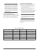
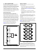
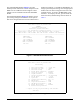
Provisioning DIP Switch Setting
A seven-position DIP switch is located on the printed
circuit board. The seven provisioning options controlled
by this switch may not be controlled via terminal
menus. The options are described in Table 3 below.
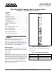
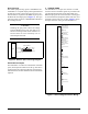
Instructions for Installing the Module
To install the T200 2-Wire HDSL2 Transceiver Unit for
the Central Office, perform the following steps:
1. Hold the unit by the front panel while supporting
the bottom edge of the module.
2. Align the unit edges to fit in the lower and upper
guide grooves for the access module slot.
3. Slide the unit into the access module slot. Simulta-
neous thumb pressure at the top and at the bottom
of the unit will ensure that the module is firmly
seated against the backplane of the enclosure.
WARNING
Up to –200 VDC may be present on telecom-
munications wiring. Ensure chassis ground is
properly connected.
When the T200 H2TU-C first powers up it runs the
power up self-tests. Once the power up self-test is
complete the status LEDs will reflect the true state of
the hardware.
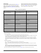
Table 3. DIP Switch Options
Switch Function On Off Default
1. Line Build Out 133-266 ft. 0-133 ft. Off
2. DS1 Signal Unframed Framed Off
3. Frame Format SF ESF Off
4. Line Code AMI B8ZS Off
5. Loopback Time Out Enabled Disabled Off
6. FT1 Loopback Enabled Disabled Off
7. Span Power Disabled Enabled Off