
Product specifications


61223006L1-5C A-1
GENERAL
HDSL2 MAINTENANCE MODES
This appendix describes operation of the HDSL2
system with regard to detection of inband and ESF
facility data link loopback codes.
Upon deactivation of a loopback, the HDSL2 system
will synchronize automatically.
Loopback Process Description
In general, the loopback process for the HDSL2 system
elements is modeled on the corresponding DS1 system
process. Specifically, the H2TUC loopback is similar to
an Intelligent Office Repeater loopback and the
H2TU-R loopbacks are similar to an in-line T1 Repeater
loopback.
In-band control code sequences are transmitted over the
DS1 link by either the unframed or overwrite method.
The HDSL2 elements respond to either method.
The unframed method produces periodic control
sequences and the normal DS1 framing bit is omitted.
The overwrite method produces periodic control
sequences. However, once per frame, the framing bit
overwrites one of the bits in the control sequence.
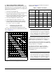
The unit can detect the loopback activation or deacti-
vation code sequence only if an error rate of 1E
-03
or
better is present.
DDS Latching Loopback Operation
If the unit is optioned for FT1 mode, then DDS Latching
Loopback operation is supported as described in
Bellcore TA-TSY-000077, Issue 3, Section 5.1.3. The
H2TU-C in the HDSL2 circuit is treated as an Identical
Tandem Dataport and the H2TU-R is treated as a
Different Tandem Dataport. The H2TU-R will
establish a network loopback upon detection of standard
DDS NI-NEI/RPTR loopback sequence.
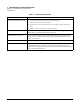
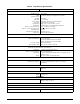
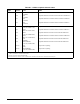
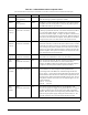
Loopback Control Codes
A summary of control sequences is given in Table A-1
and Tabl e A-2 .
NOTE
In all control code sequences presented, the
inband codes are shown leftmost bit trans-
mitted first, and the ESF data link codes with
rightmost bit transmitted first.
Appendix A
HDSL2 Loopbacks