
User's Manual


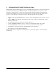

Table Of Contents

Physical Description NetVanta 150 Wireless Access Point ABG Hardware Installation Guide
20 Copyright © 2006 ADTRAN, Inc. 61700412E1-34A
2. PHYSICAL DESCRIPTION
Reviewing the Base Unit Front Panel Design
Figure 1 shows the NetVanta 150 front panel.
Figure 1. NetVanta 150 Front Panel Layout
Front Panel LEDs
The NetVanta 150 unit utilizes four LED indicators on the front panel. A single bi-color LED for the STAT
condition and three single color LEDs for the ETH, 5GHz/802.11a and 2.4GHz/802.11b/g conditions.
Table 1 describes these LEDs.
Table 1. NetVanta 150 Unit LEDs
LED Activity Indication
STAT
Green (flashing)
Unit is powering up. On power-up the STAT LED flashes until
unit is ready for service. The STAT LED also flashes during
firmware upgrade.
Green (solid) Power is on.
Red (solid) An error condition is present on the unit.
ETH Green (flashing) LAN activity is present (traffic in either direction).
Green (solid)
Powered device is connected to the Ethernet port (i.e., link
integrity).
Off
There is no LAN activity on the Ethernet port (or unit is powered
off).
5GHz/802.11a Off There is no 802.11a Wireless acitvity is detected.
Green (flashing)
Data is being transmitted or received via the 802.11a Wiresless
band. Data includes network traffic as well as user data.
2.4GHz/802.11b/g
Off There is no 802.11g or 802.11b Wireless acitvity is detected.
Green (flashing)
Data is being transmitted or received via the 802.11b/g
Wiresless band. Data includes network traffic as well as user
data.