
Installation Manual
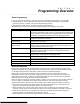

3000EN Series: Installation Instructions
2-16
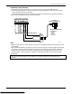
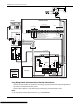
On-Board Triggers
Connect field wiring to the desired trigger pin on the 8-pin trigger connector centrally located above
the terminal strip.
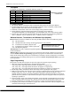
• If using 1361X10 transformer and powerline carrier devices, use the SA4120XM-1 cable (part of
4120TR Trigger Cable). See Wiring the AC Transformer section for transformer-to-trigger
connections.
• If only using the on-board triggers, you can use a 4-wire cable (N4632-4, supplied with the
control) as shown below.
U
L
If on-board triggers are used, the wiring between the control unit and the UL Listed device must be run in
conduit, be no more than 3 feet apart and have no intervening barriers or walls.
Notes
• The trigger outputs are normally high, and go low upon programmed condition.
• The outputs can be programmed for inverted operation (normally low, go high) using *79 Menu
mode.
• Program these triggers using *80/*81 Menu modes as you would for any other relay output.
• When using these outputs, note:
pin 1 = output number 17 (trigger 1):
15 ohms to ground when closed (output low), open when off (output high, normal default);
can be used to reset smoke detector power (must set “output normal low = yes” in *79 Menu
mode, and set for zone type 54, fire zone reset, in *80 Menu mode); or can support 12V relay
module
†
that draws less than 100mA
pin 5 = output number 18 (trigger 2):
100 ohms to ground when closed (output low); open when off (output high, normal default);
or can support 12V relay module that draws less than 20mA
† e.g., Altronix AX-RBS
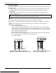
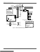
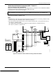
1345678
SA412OXM-1
CABLE
8-PIN TRIGGER CONNECTOR
KEY
ADT3000-006-V0
+12 AUX.
DATA
COM
SYNC
GND (-)
OUTPUT 17
(RED)
OUTPUT 18
(GREEN)
(ORANGE)
(YELLOW)
(BLUE)
(PURPLE)
(BLACK)
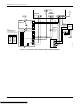
4-WIRE
CABLE
00-trigcon-005-V2
+12 AUX.
GND (-)
OUTPUT 17
OUTPUT 18
(RED)
(YELLOW)
(BLACK)
(GREEN)
1345678
8-PIN TRIGGER CONNECTOR
KEY
Figure 12. On-Board Trigger Connector with Figure 13. On-Board Trigger Connector with
SA4120XM-1 Cable for Use With 1361X10 Transformer 4-Wire Cable for Trigger Use Only