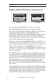
ADT Security Services, Inc. One Town Center Road Boca Raton, FL 33431 Phone: (561) 988-3600 FAX: (561) 988-3675 ADT-LCD40 Series Remote Fire Annunciators for use with Unimode 200 Addressable Fire Alarm Control Panel F IR E A LA R M A N N U N C IATO R Ack Silence Drill Hold 2 sec.
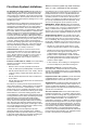
Fire Alarm System Limitations An automatic fire alarm system–typically made up of smoke detectors, heat detectors, manual pull stations, audible warning devices, and a fire alarm control with remote notification capability–can provide early warning of a developing fire. Such a system, however, does not assure protection against property damage or loss of life resulting from a fire.
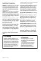
Installation Precautions WARNING - Several different sources of power can be connected to the fire alarm control panel. Disconnect all sources of power before servicing. Control unit and associated equipment may be damaged by removing and/or inserting cards, modules, or interconnecting cables while the unit is energized. Do not attempt to install, service, or operate this unit until this manual is read and understood. CAUTION - System Reacceptance Test after Software Changes.
Notes 4 Document 50520 Rev D 7/25/00 P/N 50520:D
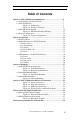
Table of Contents Table of Contents Section 1: ADT-LCD40 Series Annunciators ...........................................6 1.1 ADT-LCD40 and ADT-LCD40L ...................................................7 1.2 ADT-LCD40 Only ..........................................................................7 Figure 1-1: Components .......................................................8 Figure 1-2: Wiring to Terminals ...........................................9 1.3 SW1 DIP Switch Settings ...........................
ADT-LCD40 Series Annunciators Section 1:ADT-LCD40 Series Annunciators FIR E A LA R M A N N U N CIATO R Ack Silence Drill Hold 2 s ec. FIR E A L A R M A N N U N C IATO R Reset ADT-LCD40 ADT-LCD40L Note: Only Model ADT-LCD40L is listed for use in Canada. The ADT-LCD40 Series Annunciators are compact, attractive, 40-character, backlit LCD fire annunciators designed for use with the Unimode 200 Addressable Fire Alarm Control Panel.
ADT-LCD40 Series Annunciators 1.
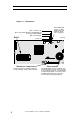
ADT-LCD40 Series Annunciators Components Figure 1-1: Components Note: OPEN (Up) position on SW1 is OFF state (See “Wiring to Terminals” on page 9.). OFF = Receive only OFF = Key-switch Disable on ADT-LCD40 only (not used on ADT-LCD40L) ROM ON = Piezo Enable Membrane Connector Piezo Sounder Cable connection to membrane switches for Acknowledge, Silence, Drill and Reset.
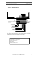
ADT-LCD40 Series Annunciators Wiring to Terminals Figure 1-2: Wiring to Terminals Side view P2 P1 Terminal Block replacement P/N 02109 Terminal Block replacement P/N 02108 + EIA-485 OUT + EIA-485 IN - EIA-485 OUT - EIA-485 IN no connection +24 VDC IN +24 VDC OUT -24 VDC IN -24 VDC OUT Earth Ground Option Note: These connections must be power-limited and the +24 VDC nominal power must be filtered and nonresettable.
ADT-LCD40 Series Annunciators 1.3 SW1 DIP Switch Settings SW1 DIP Switch Settings The Up position on DIP switch SW1 is the Off state. Refer to “DIP Switch Settings Example” on page 11, for an explanation of DIP switch positions. SW1 switch settings follow: 1 - On (Down) = Receive/Transmit, Off (up) = Receive Only. Set switch 1 to Off (Up) position for all ADT-LCD40 Series Annunciators except the last (or only) annunciator on the EIA-485 loop.
ADT-LCD40 Series Annunciators DIP Switch Settings Example . Figure 1-3: DIP Switch Settings Example Down Position = On State Up (OPEN) Position = Off State Note: SW1 DIP switch settings as illustrated in Figure 1-3 are as follows: 1. DIP switch 1: On (Down) - Receive/Transmit. This setting is used for the last or only ADT-LCD40 Series Annunciator on the EIA-485 line 2. DIP switch 2: Used on ADT-LCD40 only - On (Down) = membrane function switches enabled. 3.
ADT-LCD40 Series Annunciators 1.4 Typical Configuration Typical Configuration The ADT-LCD40 Series Annunciators mimic the Unimode 200 display, have full point-display capacity and require no programming. The ADT-LCD40 offers multiple annunciator locations with the capability of remote Acknowledge, Signal Silence, Drill and Reset functions.
Operation Display Patterns Section 2: 2.
Operation 2.2 Switch Functions for ADT-LCD40 Only Switch Functions for ADT-LCD40 Only 2.2.1 Key-switch Key-switch (shown in Off position) The key-switch is used to enable and disable the operation of the function switches if switch 2 on DIP switch SW1 has been placed ATO R to the On (Down) position. To enable the Acknowledge, Silence, Drill and Reset function switches, insert a standard ADT key into the key-switch located at the top right corner of the Reset ADT-LCD40.
Operation Switch Functions for ADT-LCD40 Only LEDs to steady on. The second press of the switch stops the scrolling and holds the event on the display for one minute. Subsequent pressing of the switch 'steps' through each active event. 2.2.3 Silence When the Silence switch is pressed and released, the ADT-LCD40 sends a signal silence command to the control panel. The Silence switch performs the same functions as the Acknowledge switch.
Operation 2.3 LED Indicators (all ADT-LCD40 Series) LED Indicators (all ADT-LCD40 Series) 2.3.1 Power This is a green LED which illuminates if AC power is applied to the host FACP. The green LED will turn off if AC power to the host FACP is lost. 2.3.2 Fire Alarm This is a red LED that flashes when one or more fire alarms occur. It illuminates steadily when an Acknowledge or Silence switch is pressed. The Alarm LED turns off when the Reset switch is pressed. 2.3.
Mounting ADT-LCD40 Series Preparation Section 3: 3.1 Mounting ADT-LCD40 Series Preparation The ADT-LCD40 Series Annunciators can be surface mounted in a three-gang electrical box such as the P/N SBB-3 (2.75" depth) or semiflush mounted in a three-gang electrical box, P/N 10103 or equivalent, with a minimum depth of 2 3/16". The ADT-LCD40 Series Annunciators cannot be mounted in three gangable electrical switch boxes connected together.
Mounting Hardware and Backboxes Figure 3-2: Hardware and Backboxes F IRE A LA R M A NN UN C IATO R A ck ADT-LCD40 Series Trim Ring S ile nce 3-Gang Electrical Box P/N 10103 (semi-flush mount) 3-Gang Electrical Box P/N SBB-3 (surface mount) Document 50520 R ese t ADT-LCD40 Series flange (replacement P/N 23165) 18 D rill Hold 2 sec.
Mounting 3.2 Semi-flush Mount Backbox Semi-flush Mount Backbox Remove the plug-in terminal blocks from the ADT-LCD40(L) circuit board. Connect the EIA-485 and power wiring into the terminal block positions illustrated in Figure 1-1 on page 8, Figure 4-1 on page 21 and Figure 4-2 on page 22. Plug the terminal blocks back into the P1 and P2 connectors on the back of the annunciator. Set DIP switch SW1 for the desired options (refer to Figure 1-2 on page 9).
Mounting 3.3 Surface Mount Backbox Surface Mount Backbox Remove the plug-in terminal blocks from the ADT-LCD40(L) circuit board. Connect the EIA-485 and power wiring into the terminal block positions illustrated in Figure 1-1 on page 8, Figure 4-1 on page 21 and Figure 4-3 on page 23. Plug the terminal blocks back into the P1 and P2 connectors on the back of the annunciator circuit board. Set DIP switch SW1 for the desired options (refer to Figure 1-2 on page 9).
ADT-LCD40 Series Electrical Connections Section 4: Power Connection ADT-LCD40 Series Electrical Connections The ADT-LCD40 Series Annunciators can be powered by the Unimode 200 24VDC nominal power or from a remote UL listed, filtered power supply such as the FCPS-24F. The power run to the annunciator must be power-limited but need not contain a power supervision relay since loss of power is inherently supervised through loss of communication with the annunciator.
ADT-LCD40 Series Electrical Connections EIA-485 Connection Figure 4-2: EIA-485 Connection ADT-LCD40 Series P1 P2 Terminal Block replacement P/N 02109 Terminal Block replacement P/N 02108 6,000 feet (1,800 m) maximum wire run from and back to FACP (3,000 feet to last ADT-LCD40) @ 18 AWG (0.75 mm2) + EIA-485 IN from source - EIA-485 IN from source (+) (-) EIA-485 Out to next ADT-LCD40 Series or return to host FACP if last or only annunciator on line Notes: 1.
ADT-LCD40 Series Electrical Connections DIM-485 Connections Figure 4-3: DIM-485 Connections Circuit Board 1 2 3 4 DIM-485 CONNECTIONS DIM-485 Terminal 1 - OUT (+) Terminal 2 - IN (+) Terminal 3 - OUT (-) Terminal 4 - IN (-) ADT-LCD40 Series3 P1 Terminal 2 - IN (+) P1 Terminal 12 - OUT (+) P1 Terminal 4 - IN (-) P1 Terminal 3 2 - OUT (-) 1. Terminal to terminal wiring is shown between the DIM-485 and one ADT-LCD40 Series Annunciator 2.
ADT-LCD40 Series Electrical Connections Wiring FACP to ADT-LCD40 Series Dim-485 Installation. CAUTION! Connect all wiring to the DIM-485 terminals before plugging it into connector J11 on the Unimode 200 circuit board. 1. Carefully align the DIM-485 connector with the four pins on connector J11 of the Unimode 200 2. Press firmly on the DIM-485 connector to seat properly on connector J11 being careful not to bend any pins 3.
EIA-485 Shield Termination Section 5: EIA-485 Shield Not in Conduit EIA-485 Shield Termination The EIA-485 circuit must be wired using a twisted, shielded pair cable with a characteristic impedance of 120 ohms (+/- 20%). Do not run cable adjacent to or in the same conduit as 120 VAC service, noisy electrical circuits that are powering mechanical bells or horns, audio circuits above 25 VRMS, motor control circuits or SCR power circuits.
EIA-485 Shield Termination EIA-485 Without Conduit Figure 5-1: EIA-485 Without Conduit Connect the drain wire to the outside of the Unimode 200 cabinet via a BXtype connector.
EIA-485 Shield Termination 5.2 EIA-485 Shield in Full Conduit EIA-485 Shield in Full Conduit The EIA-485 line allows the FACP to communicate with the ADT-LCD40 Series Annunciators. The shield for the EIA-485 line must be connected to earth ground at the FACP (both exiting and entering the FACP) but must be left floating (no connection) at the annunciator if it is the first or only device on the EIA-485 line. If a second annunciator is connected, the shield leaving the first annunciator must be floating.
Programming the Unimode 200 Section 6: EIA-485 In Conduit Programming the Unimode 200 The Unimode 200 must be programmed to allow use of the ADT-LCD40 Series Annunciators. In order to program the Unimode 200, make certain the main circuit board 'Write Protect' switch (SW1) is in the down position and then press the ENTER key on the panel keypad. After pressing ENTER, the screen shown below is displayed: 1 = PROGRAMMING 2=RD.STATUS 3=AC/BAT To enter the Programming Mode, press '1'.
Index A Acknowledge switch 6, 7, 12, 14 ADT-LCD40 6, 7, 10, 14, 15 see also ADT-LCD40 Series Annunciators software version 6 ADT-LCD40 Series Annunciators 6, 12, 13, 16, 17, 19, 20, 21, 22, 23, 28 ADT-LCD40 Series Annunciators display custom alpha labels 6 device type 6 point alarm 6 supervisory 6 system point status 6 trouble 6 zone labels 6 ADT-LCD40L 6, 7 see also ADT-LCD40 Series Annunciators Alarm LED 6, 7, 16 Alarm Silence LED 15 annunciators maximum per EIA-485 circuit 7, 12, 22 B backboxes 18 back
wiring 23 DIM-485 module 7 DIP Switch settings 8, 10, 11 function switches 11 piezo sounder 11 Receive/Transmit 10, 11 SW1 10 DIP switches 7 SW1 14, 19, 20 display scroll 14, 15 step through 15 distance from panel 7, 12, 22 Drill switch 6, 7, 12, 14, 15 E earth ground 9, 17, 25, 27 EIA-485 circuit 6, 7, 12, 19, fault 10 EIA-485 connection 22 electrical box 17, 18 electrical connections 21 electrostatic discharge 25 22, 25, 26, 27 F fault communication failure 10 FCC Part 15 requirements 24 Ferrite Core 2
Liquid Crystal Display 6 Local Authority Having Jurisdiction 8, 10 M Manual Evacuate 15 mounting 7, 17, 19 semi-flush 7 surface 7, 20 N NAC see also Notification Appliance Circuit 15 nonresettable 9 O Operation 13 P piezo sounder 7, 15 alarm resound 7 enable/disable 8, 10, 11 silence 14 trouble resound 7 power connection 21 Power LED 6, 7, 16 power source 6, 9, 12, 21 power-limited 9, 12, 21, 22 power-up 13 programming 7, 12 Unimode 200 13, 28 R Receive/Transmit 10, 11 Reset switch 6, 12, 14, 15 rese
Silence switch 6, 14, 15 software version ADT-LCD40 6 Unimode 200 6 static 25 static protection 17 supervised 21, 22 Supervisory LED 6, 7, 16 surface mount 7, 20 SW1 DIP Switch 10 switch functions 14 System LEDs 14, 15, 16 System Reset switch 7 System Status LEDs 6, 7 T terminal block 7, 9, 19, 20 three-gang electrical box 17, trim ring 17, 18, 19, 20 Trouble LED 6, 7, 16 19, 20 U Unimode 200 6, 7, 12, 13, 15, programming 28 software version 6 Unimode 200 programming 13 21, 23, 24, 26 W wire distance 2
Notes Document 50520 Rev D 7/25/00 P/N 50520:D 33
Notes 34 Document 50520 Rev D 7/25/00 P/N 50520:D
Notes Document 50520 Rev D 7/25/00 P/N 50520:D 35