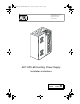
ADTAPS-6R__INSTENGLB0.fm Page 1 Tuesday, November 21, 2000 11:30 AM ADT Security Services, Inc.
Fire Alarm System Limitations An automatic fire alarm system–typically made up of smoke detectors, heat detectors, manual pull stations, audible warning devices, and a fire alarm control with remote notification capability–can provide early warning of a developing fire. Such a system, however, does not assure protection against property damage or loss of life resulting from a fire.
Installation Precautions WARNING - Several different sources of power can be connected to the fire alarm control panel. Disconnect all sources of power before servicing. Control unit and associated equipment may be damaged by removing and/or inserting cards, modules, or interconnecting cables while the unit is energized. Do not attempt to install, service, or operate this unit until this manual is read and understood. CAUTION - System Reacceptance Test after Software Changes.
ADTAPS-6R__INSTENGLB0TOC.fm Page 4 Tuesday, November 21, 2000 12:56 PM Table of Contents Table of Contents 1. Overview Introduction ..................................................................................................... 5 Description ....................................................................................................... 5 Specifications ................................................................................................... 7 2. Installation Introduction .........
ADTAPS-6R__INSTENGLB0.fm Page 5 Tuesday, November 21, 2000 11:30 AM 1. Overview Introduction This document contains information for installing, servicing, and configuring the ADT-APS-6R Auxiliary Power Supply. The table below contains a list of document sources for supplemental information: Control Panels Refer to...
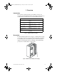
ADTAPS-6R__INSTENGLB0.fm Page 6 Tuesday, November 21, 2000 11:30 AM 1. Overview Description The figures below identify the features of the ADT-APS-6R power supply: Trouble In (J4) - Trouble Out (J3) “P” style connectors for internal cabinet connections Three 24 VDC output circuits Two (2) power-limited One (1) non power-limited Fuse F2 for battery protection (10A, 3AG, slow blow) APS-6Rsidebrd.
ADTAPS-6R__INSTENGLB0.fm Page 7 Tuesday, November 21, 2000 11:30 AM 1. Overview Specifications Specifications The ADT-APS-6R is compatible with the Unimode II, Unimode 300/400, Unimode 4-16 and Unimode 2020 control panels. Specifications for the ADT-APS-6R are: Electrical Specifications AC Primary Input Power Wire Size: #14 AWG with 600 VAC insulation 120 VAC, 60 Hz, 2.5 A 240 VAC, 50 Hz, 1.
ADTAPS-6R__INSTENGLB0.fm Page 8 Tuesday, November 21, 2000 11:30 AM 1.
ADTAPS-6R__INSTENGLB0.fm Page 9 Tuesday, November 21, 2000 11:30 AM 2. Installation ! WARNING: Use extreme caution when working with the APS-6R. High voltage and AC line-connected circuits are present. Turn off and remove all power sources. To reduce the risk of electric shock make sure to properly ground the unit. Introduction This section contains instructions for mounting, wiring, configuring and servicing the ADT-APS-6R. Installation topics covered in detail: Topic Refer to...
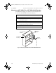
ADTAPS-6R__INSTENGLB0.fm Page 10 Tuesday, November 21, 2000 11:30 AM 2. Installation Mounting an ADT-APS-6R in a ADT-CAB-400AA Backbox Mounting an ADT-APS-6R in a ADT-CAB-400AA Backbox An Auxiliary Power Supply is mounted as shown in the figure below. To mount the ADT-APS-6R, follow these instructions: Step Action 1 Remove plastic cover from APS-6R. 2 If 240 VAC is to be used, cut JP1 jumper at this time. See "Configuring the ADT-APS-6R" on page 16.
ADTAPS-6R__INSTENGLB0.fm Page 11 Tuesday, November 21, 2000 11:30 AM 2. Installation Mounting in ADT-CAB-3 Series Cabinets Mounting in ADT-CAB-3 Series Cabinets This section contains instructions for the installation of the Auxiliary Power Supply into a ADT-CAB-3 Series cabinet (ADT-CAB-A3, ADTCAB-B3, ADT-CAB-C3 and ADT-CAB-D3). These cabinets use a CHS-4L or CHS-4 Chassis to mount the ADT-APS-6R. Instructions for mounting: Step Action 1 Remove plastic cover from APS-6R.
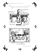
ADTAPS-6R__INSTENGLB0.fm Page 12 Tuesday, November 21, 2000 11:30 AM 2. Installation Wiring the ADT-APS-6R Wiring the ADT-APS-6R This section contains instructions for wiring the Auxiliary Power Supply as follows: • Typical field wiring from an ADT-APS-6R to a control panel and optional devices. • Wiring multiple ADT-APS-6R power supplies.
ADTAPS-6R__INSTENGLB0.fm Page 13 Tuesday, November 21, 2000 11:30 AM 2. Installation Wiring the ADT-APS-6R Connecting Multiple ADT-APS-6R Power Supplies Typical trouble bus connections for multiple ADT-APS-6R power supplies using trouble connectors J3 and J4. Use Cable 71033 or 75098 (same cables; different lengths) for all wiring. See appendix on your system for specific “Trouble Input” connection. Note: J3 and J4 can be interchanged.
ADTAPS-6R__INSTENGLB0.fm Page 14 Tuesday, November 21, 2000 11:30 AM 2.
ADTAPS-6R__INSTENGLB0.fm Page 15 Tuesday, November 21, 2000 11:30 AM 2. Installation Wiring Applications Supplying Power to a M300CADT Module The circuit is supervised and power-limited.
ADTAPS-6R__INSTENGLB0.fm Page 16 Tuesday, November 21, 2000 11:30 AM 2. Installation Configuring the ADT-APS-6R Configuring the ADT-APS-6R The ADT-APS-6R may be configured for the following: • 8-hour delay for reporting loss of AC: cut jumper JP2. • 16-hour delay for reporting loss of AC: cut jumper JP2 and JP3. • 240 VAC operation: cut jumper JP1. J9 JP2 JP3 J2 TB2 J3 J1 The figure below illustrates the location of the jumpers: JP2 JP3 APS-6Rconfig.
ADTAPS-6R__INSTENGLB0.fm Page 17 Tuesday, November 21, 2000 11:30 AM 2. Installation Servicing the ADT-APS-6R Servicing the ADT-APS-6R The only serviceable components on the ADT-APS-6R are fuses F1 and F2. If a fuse fails, replace it with a fuse of the same type and rating: • F1 AC protection - 4A, 3 AG • F2 Battery protection - 10A, 3 AG To replace either fuse remove the vertical PC board as follows: 1. Turn off and remove all power sources. 2. Remove plastic cover. 3.
ADTAPS-6R__INSTENGLB0.fm Page 18 Tuesday, November 21, 2000 11:30 AM 2.
ADTAPS-6R__INSTENGLB0.fm Page 19 Tuesday, November 21, 2000 11:30 AM Appendix A - Unimode 4-16 Connecting the ADT-APS-6R to an MPS-24B Make the following connections as shown in the figure below.
ADTAPS-6R__INSTENGLB0.
ADTAPS-6R__INSTENGLB0.fm Page 21 Tuesday, November 21, 2000 11:30 AM Appendix B - Unimode 300/400 Connecting the ADT-APS-6R to an MPS-400 Make the following connections as shown in the figure below.
ADTAPS-6R__INSTENGLB0.
ADTAPS-6R__INSTENGLB0.fm Page 23 Tuesday, November 21, 2000 11:30 AM Appendix C - Unimode II & Unimode 2020 Connecting the ADT-APS-6R to an MPS-24A Make the following connections as shown in the figure below.
ADTAPS-6R__INSTENGLB0.fm Page 24 Tuesday, November 21, 2000 11:30 AM Appendix C - Unimode II & Unimode 2020 Connecting the ADT-APS-6R to an MPS-24B Connecting the ADT-APS-6R to an MPS-24B Make the following connections as shown in the figure below.
ADTAPS-6R__INSTENGLB0IX.
ADTAPS-6R__INSTENGLB0IX.