
- ARESCOM NetDSL 800 ADSL Modem version 5.2b1 User's Guide
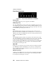
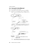
Table Of Contents
- Heading1TOC - 1. Before You Begin
- Heading1TOC - 2. Hardware Installation
- Heading1TOC - 3. Software Installation
- Heading1TOC - 4. NetDSL Manager
- Heading1TOC - 5. Configuration
- Heading1TOC - 6. Status Feature
- Heading1TOC - 7. Tools Feature
- Heading1TOC - 8. Troubleshooting
- Heading1TOC - Appendices
- Heading1 - Before You Begin
- Heading1 - Hardware Installation
- Heading2 - 2.1 Diagram of the NetDSL
- Heading2 - 2.2 Safety First
- Heading2 - 2.3 Setup Instructions
- Heading2 - 2.4 Connect to the Ethernet
- 1Step - Step 1. Locate your Ethernet cable (included).
- Step - Step 2. Attach the Ethernet cable to the Ethernet interface of your NetDSL.
- Step - Step 3. Plug in the loose end of the Ethernet cable to your Ethernet network.
- Figure - Figure 2.3 Connecting to a Ethernet Port on a PC
- Figure - Figure 2.4 Connecting to the Uplink Port on a Network Hub
- Figure - Figure 2.5 Connecting to the Non-Uplink Port on a Network Hub
- Heading2 - 2.5 Connect to the ADSL Interface
- Heading2 - 2.6 Connect to the USB Interface
- 1Step - Step 1. Plug the Type-B (square-shaped) end of the USB detachable cable (included) into t...
- Step - Step 2. Plug the Type-A (flat-shaped) end of the USB detachable cable into the USB port of...
- Step - Step 3. Do not turn on the power switch until software installation is complete. Proceed t...
- Figure - Figure 2.7 Connecting to the USB Interface
- Heading2 - 2.7 Connect to Power
- Heading1 - Software Installation
- Heading2 - 3.1 About TCP/IP
- Heading2 - 3.2 Detecting TCP/IP in Windows® 95/98
- Heading2 - 3.3 Installing TCP/IP in Windows® 95/98
- 1Step - Step 1. From the Configuration tab in the Network window, click Add.
- Step - Step 2. Select Protocol for the type of network component, and click Add.
- Step - Step 3. Choose Microsoft for Manufacturers list box and TCP/IP for Network Protocols list ...
- Step - Step 4. Check to see TCP/IP is listed under Network Components.
- Heading2 - 3.4 Configuring TCP/IP in Windows® 95/98
- 1Step - Step 1. From the Configuration tab, select TCP/IP (for Ethernet adapters) listed under Ne...
- Step - Step 2. Select the IP Address tab.
- Step - Step 1. Click Obtain an IP Address automatically.
- Step - Step 2. OPTIONAL* Click the DNS Configuration tab and select Disable DNS. If you previousl...
- Step - Step 3. Select the Gateway tab and then click Remove to clear all pre-existing settings.
- Step - Step 4. Click OK to exit TCP/IP Properties window and click OK to exit Network window. Whe...
- 1Step - Step 1. Click Specify an IP Address and then type the IP Address and Subnet Mask (for you...
- Step - Step 2. Click the Gateway tab.
- Step - Step 3. Type in your Gateway IP Address (the LAN IP address for the NetDSL) from your ISP ...
- Step - Step 4. Click the DNS tab. Enter the Host name, Domain name, and DNS Service Search Order ...
- Step - Step 5. Click OK to exit TCP/IP Properties window and click OK to exit Network.
- Step - Step 6. When prompted, restart Windows® 95/98. If you are not prompted to restart Windows®...
- Heading2 - 3.5 Detecting TCP/IP in Windows® 2000
- 1Step - Step 1. Turn on your computer and log-in to Windows 2000.
- Step - Step 2. Click the Start button and select Settings.
- Step - Step 3. Choose Control Panel, and then double click Network and Dial-up Connections icon
- Step - Step 4. Double click on the Local Area Connection icon. In the Local Area Connection Statu...
- Step - Step 5. In the Local Area Connection Properties window:
- Heading2 - 3.6 Installing TCP/IP in Windows 2000
- 1Step - Step 1. From the General tab in the Local Area Connection Properties window, click Install.
- Step - Step 2. In the Internet Protocol (TCP/IP) Properties window, select the Protocol icon for ...
- Step - Step 3. Choose the Internet Protocol (TCP/IP) icon from the Network Protocol list box, the...
- Step - Step 4. Check to see if Internet Protocol (TCP/IP) is listed under Network Components.
- Heading2 - 3.7 Configuring TCP/IP in Windows® 2000
- 1Step - Step 1. From the General tab in the Local Area Connection Properties window, select Inter...
- 1Step - Step 1. Click Use the following IP Address and then type the IP Address, Subnet Mask, and...
- Step - Step 2. Enter the Preferred and Alternate DNS server IP addresses.
- Step - Step 3. Click OK to exit the Internet Protocol (TCP/IP) Properties window. Proceed to Chap...
- Heading2 - 3.8 Detecting TCP/IP in Windows® NT 4.0
- Heading2 - 3.9 Installing TCP/IP in Windows® NT 4.0
- Heading2 - 3.10 Configuring TCP/IP in Windows® NT 4.0
- 1Step - Step 1. From the Protocols tab, select TCP/IP (for Ethernet adapters) listed under Networ...
- Step - Step 2. Select the IP Address tab.
- Step - Step 1. Click Obtain an IP Address from DHCP Server.
- Step - Step 2. OPTIONAL* Click the DNS tab and select Disable DNS. If you previously entered any ...
- Step - Step 3. Click OK to exit Network Properties window. Proceed to Chapter 4 “NetDSL Manager.”
- Step - Step 1. To enable static addressing, click Specify an IP Address and then type the IP Addr...
- Step - Step 2. Click the DNS tab. Enter the Host name, Domain name, and DNS Service Search Order ...
- Step - Step 3. Click OK to exit Network Properties window. Proceed to Chapter 4 “NetDSL Manager.”
- Heading2 - 3.11 Installing the Software Drivers
- 1Step - Step 1. After your PC detects an USB connection, a message window appears to indicate tha...
- 1Figure - Figure 3.1 USB Installation Step 1
- Figure - Figure 3.2 USB Installation Step 2
- Figure - Figure 3.3 USB Installation Step 3
- Figure - Figure 3.4 USB Installation Step 4
- Figure - Figure 3.5 USB Installation Step 6
- Figure - Figure 3.6 USB Installation Step 7
- Heading1 - NetDSL Manager
- Heading2 - 4.1 Installing the NetDSL Software
- 1Step - Step 1. Start Windows® 95/98 or Windows® NT 4.0.
- Step - Step 2. Insert the included ARESCOM CD into your CD-ROM drive
- Step - Step 3. Click Start, then choose Run.
- Step - Step 4. Click the Browse button, and look in your CD-ROM drive.
- Step - Step 5. Select the ARESCOM folder, and then the NetDSL Manager folder.
- Step - Step 6. Select the setup.exe file and click the Open button.
- Step - Step 7. Click the OK button.
- Heading2 - 4.2 Launching the NetDSL Manager
- StepNumOnly - 1. Multiple Routers/Bridges Selection— provides the number of and basic information...
- StepNumOnly - 2. NetDSL Manager— is the main software that allows you to configure, maintain and ...
- 1Figure - Figure 4.1 Multiple Routers/Bridges Selection
- Figure - Figure 4.2 Subnet window
- Figure - Figure 4.3 NetDSL Manager
- 1TableTitle - Table4.1 Keyboard Keys to Activate NetDSL Features
- Heading2 - 4.1 Installing the NetDSL Software
- Heading1 - Configuration
- Heading1 - Status Feature
- Heading1 - Tools Feature
- Heading1 - Troubleshooting
- Heading1 - About
- Heading1 - Configuration
- Heading1 - Parameters
- Heading1 - Ethernet
- Heading1 - Cable Pinout
- Heading1 - Warranty
- Heading1 - Information
- Heading1 - Declaration of Conformity
Hardware Installation
2-2
NetDSL Software User’s Guide
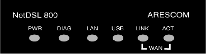
Front Panel Interfaces
Figure 2.2 Front Panel Interfaces for NetDSL
PWR (Power)
A green LED is ON when power is supplied to the NetDSL.
DIAG (Diagnostic)
The yellow DIAG LED is an indicator that shows the NetDSL modem has been
successfully booted up and the software is functional. When NetDSL is powered
on, the DIAG LED flashes while the router is booting up. After 10 to 15 seconds,
the DIAG LED stops flashing and remains off.
LAN
The LAN LED displays the LAN connection between the modem and your
Ethernet network. The green LED remains solid while there is a connection to the
10BaseT system. The green LED flashes when data is being transmitted between
the modem and the Ethernet system.
USB
The USB LED displays the USB connection between the modem and your PC.
The yellow LED flashes slowly if the USB line is being trained. The yellow LED
remains solid if the USB line is trained and ready between the PC and the
modem. A flashing yellow LED indicates data activity between your PC and the
modem. If the data traffic is heavy, the frequency of the flashing yellow LED
becomes higher and will appear solid.
WAN LINK
Displays the connection between the modem and the remote DSL network. The
green LED flashes slowly if the DSL line is not connected or is being trained.
The green LED remains solid if the DSL line is trained and ready between the
modem and the remote switch.
WAN ACT (Activity)
A flashing yellow LED indicates data activity between the DSL network and the
modem. If the data traffic is heavy, the frequency of the flashing yellow LED
becomes higher and will appear to be solid.