ADS® XiLog+ System User Manual August 2011 QR 775026 A0 ADS LLC 1300 Meridian Street, Suite 3000 Huntsville, AL 35801 Telephone (256) 430-3366 / Fax (256) 430-6633 www.adsenv.
ADS XiLog+ System User Manual Copyright © 2011 ADS® LLC. All rights reserved. ADS® is a registered trademark of ADS LLC. PrimeWorks® is a registered trademark of Primayer Limited. Microsoft® and Windows® are registered trademarks of Microsoft Corporation. All other brand and product names are trademarks or registered trademarks of their respective holders. Notice of Proprietary Information The information contained herein represents the latest information available at the time of publication.
ADS XiLog+ System User Manual Table of Contents Chapter 1 System Overview .............................................................. 1 Features ........................................................................................................4 Applications .................................................................................................5 PrimeWorks Software ..................................................................................6 Software Requirements ...................
ADS XiLog+ System User Manual Logger Period .......................................................................................27 Additional Notes ..................................................................................27 Installation..................................................................................................28 Commissioning Mode ..........................................................................28 Read Current Values ..............................................
ADS XiLog+ System User Manual Meter Reading ......................................................................................40 Meter Units ..........................................................................................40 Secondary Logging ..............................................................................40 Alarm Configuration ..................................................................................42 Enabled .............................................................
ADS XiLog+ System User Manual vi
ADS XiLog+ System User Manual CHAPTER 1 System Overview The ADS® XiLog+ is a telemetric data logger that communicates through the GSM (Global System for Mobile) cellular radio network using either SMS (Short Messaging Service) or GPRS (General Packet Radio Service). The XiLog+ is available from the factory with either a quad band antenna or a connector to receive an external antenna.
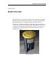
ADS XiLog+ System User Manual XiLog+ installed in ground The XiLog+ is available in the following configurations: XiLog+ Model 1F 1P 2i 2 3i 9 Total number of channels 1 1 2 2 3 9 Number of bi-directional flow channels 1 1 1 1 2 Number of analog channels (transducer: voltage or current input) Number of internal pressure channels Current Inputs: 0-10mA and 4-20mA Voltage Inputs: 0-2V, 0-5V, 0-10V Analog Channel Accuracy: ± 0.
ADS XiLog+ System User Manual Example of XiLog+ installation Note: The battery packs in the XiLog+ are designed to last 5 years. However, data logger configuration and usage will impact the estimated battery life. Therefore, ADS does not guarantee that all battery packs will last for 5 years. Refer to Appendix C: Battery Life on page 69 for more information. Caution: The XiLog+ contains Lithium batteries and radio transmitters. These batteries must be removed before shipping the unit by air.
ADS XiLog+ System User Manual Features 4 Logs average data at 1-second to 24-hour intervals and flow totals, minimum, and maximum values for 24-hour periods Provides cyclic logging for continuous, indefinite data collection. New data begins overwriting the oldest records once the memory is full. Standard memory size of 1GB accommodates data storage for 200 million readings.
ADS XiLog+ System User Manual Applications Flow monitoring leakage control (water loss reduction) demand management domestic and industrial use Hydraulic network modeling Pressure monitoring PRV (pressure reducing valve) performance monitoring Reservoir and bore-hole depth measurement River level measurement Depth-to-flow conversion Rainfall measurement Overflow detection 5
ADS XiLog+ System User Manual PrimeWorks Software Use the PrimeWorks® software to configure the XiLog+ and manage the data collected from the unit. The management capabilities include reporting and graphing functions. Note: Do not run other applications on the PC or laptop computer during the PrimeWorks software installation process. Software Requirements ADS requires the following software for proper operation of the PrimeWorks software: Microsoft® Windows® XP or later Microsoft .
ADS XiLog+ System User Manual SIM Card To perform wireless communication via GSM, the XiLog+ must be equipped with a SIM card similar to the card used in a cellular phone. SIM cards are available through a local service provider. However, please contact ADS before ordering a SIM card. Technologies and business practices vary among providers; therefore, some provider’s services may not be compatible with the XiLog+ system.
ADS XiLog+ System User Manual Removing the SIM Holder from the XiLog+ 1. Loosen the 4 screws securing the cover plate in position. 2. Remove the cover plate. 3. Push on the SIM release button. This should cause the SIM holder to protrude slightly from the slot. 4. Remove the SIM holder from the logger.
ADS XiLog+ System User Manual Removing the SIM Card from the SIM Holder (applies only to replacement) 1. Without touching the contacts on the SIM card, gently push an object through the hole in the SIM holder. 2. Remove the SIM card. Inserting a SIM Card into the SIM Holder Without touching the SIM card contacts, insert the SIM card into the SIM holder, aligning the beveled edge of the card with the keyed corner of the SIM holder and facing the gold contacts on the card outward.
ADS XiLog+ System User Manual Technical Support ADS provides comprehensive technical support to assist customers in the configuration and operation of the XiLog+. Please contact ADS Client Services by email at adssupportcenter@idexcorp.com or by phone at (877) 237-9585 for assistance, when necessary.
ADS XiLog+ System User Manual ADS No-Hassle Warranty and Return Policy The following sections detail the hassle-free warranty and return policy for the ADS XiLog+. New Product Warranty ADS will repair or replace any XiLog+ equipment (supplied by ADS) that is defective in materials and/or workmanship for up to two (2) years following the date of shipment from ADS. To make a warranty claim, the customer should simply call ADS at (256) 430-3366 or contact ADS Client Services toll-free at (877) 237-9585.
ADS XiLog+ System User Manual Product Returns If the customer is not satisfied with the performance of the XiLog+ system, the customer may return the equipment within 30 days for a full refund, provided the condition of the equipment is in the same condition as sold, except for expected or normal wear and tear for the period of use.
ADS XiLog+ System User Manual CHAPTER 2 Deploying the XiLog+ Deploying an ADS XiLog+ logger typically involves the involves the following steps: 1. Programming the XiLog+ 2. Performing a Signal Strength Test 3. Installing the XiLog+ at the Location Deploy XiLog+ data loggers in a similar manner to other comparable units. However, consider the following factors concerning GSM capabilities and requirements during deployment: • Mount the logger in an upright position, not at an angle or on its side.
ADS XiLog+ System User Manual Programming the XiLog+ Configure the XiLog+ using the PrimeWorks software. Refer to Programming the Logger Using PrimeWorks on page 21 for more information and instructions. Note: The logger also may be programmed using the XiLog+ FastTrack software. Refer to Appendix A: XiLog+ FastTrack Software on page 62 for brief instructions on programming a logger using this simple application.
ADS XiLog+ System User Manual 4. Select the Change Frequency checkbox, and then choose the appropriate frequency for the network from the corresponding dropdown list. 5. Select the Change GPRS Configuration checkbox, and enter the username, password, and gateway (APN) setting for GPRS internet access obtained through the network provider in the corresponding fields. 6. Click on the Program button to program the selected logger with the designated frequency and GPRS configuration currently displayed. 7.
ADS XiLog+ System User Manual Performing a Signal Strength Test GSM network coverage can vary considerably both day-to-day and locationto-location. Therefore, XiLog+ data loggers are equipped with a GSM signal strength test feature for assessing the logger’s ability to establish contact with the GSM network from the site during the deployment process. The test includes deploying the data logger and then measuring the GSM signal strength a designated number of times at established intervals.
ADS XiLog+ System User Manual XiLog+ to another site. If another site is not available or a new location produces similar results, ADS recommends deploying a XiLog+ equipped with an external antenna. The signal strength test is now complete. 6. Deploy the XiLog+, if appropriate.
ADS XiLog+ System User Manual Installing the XiLog+ Installation primarily involves connecting the cables to the inputs on the XiLog+ and mounting the logger. Sensors and cables supplied by ADS come with the appropriate connector from the factory. However, when necessary, ADS can attach an appropriate connector to a sensor supplied by another manufacturer. For information, assistance, or questions regarding installation, please contact ADS Client Services by email adssupportcenter@idexcorp.
ADS XiLog+ System User Manual Internal Pressure Transducer Loggers equipped with an internal pressure transducer have a male quickrelease connector. The integrated pressure transducer is available in the following ranges: 0-145 PSI (0-10 Bar) or 0-290 PSI (0-20 Bar). Subjecting the transducer to pressures of more than 150% of its range may damage the sensor.
ADS XiLog+ System User Manual 20
ADS XiLog+ System User Manual CHAPTER 3 Programming the Logger Using PrimeWorks Use the PrimeWorks software to program and readback (or collect) data from the XiLog+. Various other graphing, reporting, and export functions also are available through PrimeWorks. A separate XiLog+ FastTrack application also is available through ADS for programming the more standard features of the data logger in a more expeditious manner.
ADS XiLog+ System User Manual Launching the PrimeWorks Software Prior to launching the PrimeWorks software, connect the XiLog+ to the computer using the USB cable. Once connected, select Start > All Programs > Primayer > PrimeWorks > PrimeWorks from the Windows start menu or double-click on the PrimeWorks icon on the Windows desktop to launch the software. Note: The ordering of these steps is inconsequential. Therefore, the XiLog+ also can be connected to the USB after launching the PrimeWorks software.
ADS XiLog+ System User Manual Connected Loggers Multiple loggers can be connected to the computer simultaneously via USB. For multiple loggers, move among the individual logger configurations by selecting the appropriate logger from the Connected Loggers drop-down list. Selecting a logger displays a group of headers representing windows corresponding to the various configuration, communication, and reporting functions of the logger. Access the contents of a window by clicking on the associated header.
ADS XiLog+ System User Manual Communications The Communications window controls all the communications with the logger. It includes options for collecting data (i.e., readback) from a logger and programming a logger with a new configuration. Program All Selecting this button sends the currently selected program settings to the logger and deletes all data from the logger.
ADS XiLog+ System User Manual From Last Readback Choosing this radio button ensures PrimeWorks collects only the data recorded by the logger since the last readback was performed. Note: Clicking on the Quick Readback button on the title bar or the Readback button corresponding to a logger in the Connected Loggers drop-down list accomplishes the same operation as selecting the From Last Readback option.
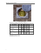
ADS XiLog+ System User Manual Logger Information Logger Information window Name This editable field contains the name that will appear in the PrimeWorks database for the selected logger. Change or edit the name as necessary. Site ID This editable field displays a unique ID that can be programmed into the logger. The logger includes this name with the name of the site when transmitting data via FTP. Phone Number This editable field displays the phone number of the logger.
ADS XiLog+ System User Manual Logger Period This section indicates the date and time period for which the logger records data. Start Immediately Selecting this radio button initiates logging immediately once logger programming is complete and continues logging indefinitely. Custom Dates Selecting this radio button initiates and sustains logging for the date/time range designated in the Logging Start and End Time fields.
ADS XiLog+ System User Manual Installation Installation window This window includes all the parameters relevant to installing the logger at the site. Commissioning Mode This drop-down list contains the options available for communication: Commissioning Mode menu options On Selecting this option places the logger in commissioning mode. This mode ensures the logger remains powered up, connected to the GSM network, and available for communication.
ADS XiLog+ System User Manual Freight Mode Selecting this mode prevents the modem from powering up so that the logger cannot transmit, even when the logger has been programmed to transmit (e.g., because of an alarm). Select this option when air freighting a logger, even if the SIM card has been removed. ADS ships all loggers transported by air in this mode.
ADS XiLog+ System User Manual External Power Voltage This field displays the external power voltage measured by the logger. If the logger is attached via USB, PrimeWorks will display the USB voltage being supplied to the logger (typically 5 volts). If the voltage is requested remotely, PrimeWorks will display the voltage coming from the external power supply.
ADS XiLog+ System User Manual Start Test Selecting this button initiates the signal strength test. The logger will begin measuring the signal strength once the delay period has passed. A counter will count down the time until the test is due to begin to allow sufficient time for placing the logger in the appropriate position. This counter also will be used to identify the end of the test. When the test is complete, recover the logger and read the results.
ADS XiLog+ System User Manual Analog Channel – Internal Pressure Channels (Analog Pressure) window This window includes the parameters for setting up the internal pressure transducer channel. A green dot next to the channel name indicates the channel is enabled and recording data. Enable Channel Selecting this checkbox enables the channel on the logger. Not all channels on a logger must be enabled when it is in use. Disabled channels do not use power.
ADS XiLog+ System User Manual Data Type This drop-down list contains the options for selecting the type of data that will be recorded through the channel. Custom Offset This field indicates the offset. Modify this value (when necessary) manually or using the up/down arrows. For example, enter the value representing the offset for adding the ground level to all pressure values.
ADS XiLog+ System User Manual Analog Channel – Generic This window includes the parameters for setting up the generic analog channels present on the XiLog+ 2 and XiLog+ 9 models. Three options are available based on the channel capabilities: current, millivolt, and voltage. If the channel can support all three options, a drop-down menu allows for selection of the one to use. Each option requires a different type of cable to interface to the sensor.
ADS XiLog+ System User Manual Generic Analog – MilliVolt example Enable Channel Selecting this checkbox enables the channel on the logger. Not all channels on the logger must be enabled when the logger is in use. Disabled channels do not use power. Sensor Type This drop-down includes the options for selecting the sensor type (Current, MilliVolt, or Voltage). Selecting the Voltage or Current also requires selection of the Electrical Range. Refer to Electrical Range on page 36.
ADS XiLog+ System User Manual PCAL (applicable only to the MilliVolt sensor type) This pressure calibration value represents the number of millivolts at full range. This value is unique for each sensor, and sometimes is referred to as Full Scale Detection (FSD). Custom Offset (applicable only when measuring pressure, height, or depth) This field indicates the offset added to all readings. For example, enter the appropriate value to add to all pressure values to compensate for ground level.
ADS XiLog+ System User Manual Send Data Reports Selecting this option ensures the logger sends data reports by SMS or GPRS based on the frequency selected for remote data reporting. The minimum logging interval for data sent through SMS is 1 minute. Activating SMS reporting for data based on a shorter logging interval requires averaging the data at a 1-minute interval before being sent.
ADS XiLog+ System User Manual Digital Channel This window includes the parameters for setting up digital channels. The presence of a green dot to the left of the channel name indicates the channel is enabled and recording data. Enable Selecting this checkbox enables the channel on the logger. Not all channels on a logger must be enabled when the logger is in use. Disabled channels do not use power.
ADS XiLog+ System User Manual Several options also are included in the Sensor Types drop-down list for performing event logging using digital sensors. To implement event logging, select one of the corresponding options from the list. Pulse Direction This drop-down list contains the options for specifying how a bidirectional sensor indicates reverse flow. Logging Interval This drop-down list includes the options for designating the measurement interval at which to log data on this channel.
ADS XiLog+ System User Manual If this option is not selected, the flow rates from the two meters will be logged and transmitted independently. Therefore, transmitting the data via SMS will result in sending double the number of SMS. Send Data Reports Selecting this checkbox ensures the logger sends data reports by SMS or GPRS, based on the interval designated for remote data reporting. The minimum logging interval for data sent through SMS reporting is 1 minute.
ADS XiLog+ System User Manual internally and remotely requested (as required). Select the Enabled checkbox to enable the associated fields, and then enter the second interval at which to log the data and designate whether to transmit the data obtained at this interval during data reporting activities.
ADS XiLog+ System User Manual Alarm Configuration Alarm Configuration sub-window Alarms may be setup independently for each channel of the logger. Three types of alarms are available: threshold, profile, and envelope alarms. Enabled Selecting this checkbox activates the alarms for this channel. Profile Mode Profile Mode menu options This drop-down contains the options for selecting the kind of alarm to generate from the XiLog+ under certain threshold conditions for a channel.
ADS XiLog+ System User Manual Deadband (applicable only to Threshold and Profile alarms) This field displays the deadband value around the threshold. The logger will generate a high alarm when the channel reading exceeds the High Threshold plus the deadband. The alarm clears when the channel reading falls below the High Threshold and the deadband. For example, entering a high threshold of 0.456 mgd and a deadband of 0.023 mgd will trigger a high alarm when the flow exceeds 0.
ADS XiLog+ System User Manual Threshold Alarms Threshold alarms generally involve designating a high and/or low threshold beyond or below which the XiLog+ will generate an alarm. This section includes descriptions for the parameters that are common only to threshold alarms. Low Threshold This field represents the threshold below which the logger will trigger a low alarm. Enter the threshold manually or use the up/down arrows.
ADS XiLog+ System User Manual Merge multiple days Choose this option to import data for several days, and then designate the start and end dates representing the date range for which to import the data using the Start Date and End Date calendar controls. Note: The calendar controls only allow the selection of dates for which data is available. When multiple days are selected, the system will average the data for each time period for every day in the range.
ADS XiLog+ System User Manual Disabling a value on the graph Enable the alarms for this profile period again by deselecting the Disable Selected Profile checkbox. After entering the required profile, select the deadband and debounce delay (when necessary). The deadband around the profile can represent either a single value or a percentage. When it represents a percentage, the value entered for the deadband corresponds to the percentage of the profile value.
ADS XiLog+ System User Manual Using the Autofit option for Envelope alarms This provides the flexibility to change the values used to generate the high and low alarms for each period independently. Select, change, move, and disable specific values using the same methods applied for standard profiles.
ADS XiLog+ System User Manual Remote Data Reporting Remote Data Reporting window This window includes the parameters for setting up remote delivery of data from the XiLog+ to the designated host system(s). Message Type This drop-down list contains the options for selecting the delivery method (SMS or FTP using GPRS technology) through which the XiLog+ will send data. Selecting SMS sends reports to as many as 3 host numbers (when applicable).
ADS XiLog+ System User Manual Ignore Daylight Savings Selecting this checkbox prevents the clock in the XiLog+ from compensating for daylight savings time. Host and Alarm Numbers When performing remote data reporting via SMS, the XiLog+ transmits the data to all the host numbers designated in the Contact Details section. A host number corresponds to a GSM modem connected to a computer.
ADS XiLog+ System User Manual FTP Password This field represents the password for logging onto the FTP server. Enter the appropriate password for the user. Test Login Details Clicking on this button verifies the FTP server address, username, and password by attempting to call and log into the server. PrimeWorks will provide notification of success or failure. A failure may indicate the wrong server address or login information.
ADS XiLog+ System User Manual Data Transmission at Other Intervals Programming the logger to perform data transmission using a different regime requires selecting or setting several parameters: 1. Select the interval at which to send the data from the Transmission Frequency drop-down list. 2. Designate the period of time within which the logger should conduct data transmission in the Start and End fields.
ADS XiLog+ System User Manual Optional Receive Frequency Window Standby Window This window exists for applications where the XiLog+ will provide constant power to the modem so that it is available to accommodate instantaneous requests for data.
ADS XiLog+ System User Manual CHAPTER 4 Battery Replacement 1. Carefully unscrew the yellow cover of the XiLog+ counter-clockwise 1/8 of a turn and lift it off the housing. 2. Carefully lift out the antenna and circuit board from the housing. 3. Disconnect or unplug the battery from the board. 4. Remove the screws securing the battery holder to the housing.
ADS XiLog+ System User Manual 5. Remove the battery holder from the housing. 6. Remove the battery from the holder.
ADS XiLog+ System User Manual 7. Feed the battery cable from the new battery through the hole in the battery holder. 8. Place and properly position the battery into the holder. 9. Insert the battery holder back into the XiLog+, and secure it with the two screws. 10. Connect the battery cable to the circuit board. 11. Slide the circuit board into the rails inside the housing. 12. Place the yellow cover back onto the XiLog+ and into position. 13. Turn the yellow cover clockwise 1/8 of a turn.
ADS XiLog+ System User Manual 56
ADS XiLog+ System User Manual CHAPTER 5 9-Channel Connections Two options are available for wiring the outputs on the XiLog+ 9: • NXG-302 Expansion Box • NXG-303 Bare Wire Cable NXG-302 Expansion Box ADS offers an expansion box for the wiring. Make connections based on the figures below. Seal any unused connectors on the box with a blank to prevent damage to the connection box.
ADS XiLog+ System User Manual Note: Each voltage input has a 2-, 5-, or 10-volt range, based on the position of the jumper next to the appropriate input. Verify the correct position. Selecting the wrong position could result in damage to the logger.
ADS XiLog+ System User Manual R represents the following: V= 0-2 volts; R=0Ω V= 0-5 volts; R=69k8Ω, ±0.1%, 25ppm V= 0-10 volts; R=187k Ω, ±0.
ADS XiLog+ System User Manual 60
ADS XiLog+ System User Manual CHAPTER 6 Appendices This chapter contains important instructional and reference information regarding the XiLog+ FastTrack software, meter scaling, battery life, and airfreight restrictions.
ADS XiLog+ System User Manual Appendix A: XiLog+ FastTrack Software The XiLog+ FastTrack software primarily is designed for expediting the process of programming the logger, viewing the current logger configuration, and testing the signal strength. Although the PrimeWorks configuration process is much more comprehensive, FastTrack represents an efficient and effective alternative for deploying and/or testing the logger quickly in the field.
ADS XiLog+ System User Manual Viewing the Current Configuration To view the current configuration programmed into the logger, click on the View button at the bottom of the XiLog+ FastTrack application window. Programming the Logger 1. Edit the name of the logger in the Site Name field, when necessary. 2. Edit the phone number (when applicable) in the Phone Number field. 3.
ADS XiLog+ System User Manual Select the interval at which the data will be logged and averaged (as necessary) from the Interval drop-down list. Sending 5- or 10minute data will require sending more than one SMS per channel per day. Choosing Off will prevent the channel from recording measurements. 5. Designate the parameters under the Pressure Channel 1 header in the following way: Select the unit of measure in which to log the data from the Units drop-down list.
ADS XiLog+ System User Manual 7. Verify the settings and readings returned. Edit the settings as necessary, and consider the following: The Flow Channel header displays the current flow and meter readings. These updates every 10 seconds. If the flow rate does not match the meter reading, edit the FCAL value as necessary and click on the red arrow to send the new value to the logger. Edit the Meter Reading as necessary and click on the corresponding red arrow to send the new value to the logger.
ADS XiLog+ System User Manual Appendix B: Meter Scaling Tables Elster/Kent Helix & Domestic Meters Meter Helix 2000 Helix 3000 Master 2000 PU10/LRP (mm) FCAL 40-80 10 100-300 100 40-80 10 100 10 150 100 40-50 1 80-100 10 PG100 Helix 4000 80-125 10/1000 150-300 100/10000 PSM PSM-PS15-PS20 (V100) 15/20 0.5 PSM-PS25-PS30 (V100) 25-30 5 40 5 15 & 20 0.
ADS XiLog+ System User Manual Meter CYBLE LF (mm) K=2.5 K=10 K=25 FlostarM 40-100 25 100 250 Woltex 50-100 25 100 250 150-300 250 1000 2500 400-500 2500 10000 25000 Sensus (Socam/Meinecke) Meter K510 (mm) 510/510PR 15-20 FCAL 1 501L 10 501LM 100 501JM 1000 510/510PR 25-30 501JM K505R 10 0.5 5 100 R01.
ADS XiLog+ System User Manual ** Applies only to 7-digit counters; the other FCALs apply to the 8-digit counters. Kent combination meters use a Helix 3000 meter as the main meter and a PSM-T as the secondary meter. Select the appropriate FCAL from the table above for each meter. The Master 2000 has been discontinued. Socam meters: *The 510 pulse unit is factory installed and cannot be removed. The FCAL is determined at the factory, and the table above displays the values available.
ADS XiLog+ System User Manual Appendix C: Battery Life Measurement Interval Transmission Standard Internal Battery Double Internal Battery External Lithium Battery ≥1 minute Once per day >5 years >10 years ≥1 minute Once per hour >1.2 years >2.5 years >7 years ≥1 minute Once every 15 minutes (for 10 hours a day) >0.7 year >1.5 years >5 years ≥1 minute Once every 15 minutes 0.3 year 0.7 year 2.
ADS XiLog+ System User Manual Appendix D: Airfreight Restrictions APP3.1: Essential Safety Precautions before Air Freighting To prevent radio transmission on aircraft, remove the batteries and the removable external antenna (when applicable) from the equipment before transporting this product by air. IATA Hazardous Goods Regulation This product is powered by a battery containing lithium D-cells.