ADS® Portable FlowShark® Pulse Installation, Operation, and Maintenance Manual February 2013 QR 775006 A2 An introductory guide to the ADS® Portable FlowShark® Pulse Meter Valid as of Firmware Revision No. 4.00 1300 Meridian Street, Suite 3000 Huntsville, AL 35801 USA (256) 430-3366 www.adsenv.
ii ADS Portable FlowShark Pulse Manual © 2013 ADS® LLC. All rights reserved. ADS®, ADS Environmental Services®, and FlowShark® are registered trademarks of ADS LLC. NIVUS® is a registered trademark of NIVUS GmbH. Microsoft®and Excel® are registered trademarks of Microsoft Corporation. Allen® is a registered trademark of Apex Tool Group LLC. Hastelloy® is a registered trademark of Haynes International, Inc. Viton® is a registered trademark of DuPont Performance Elastomers.
Table of Contents iii Table of Contents Chapter 1 Introduction 1-1 Declaration of Conformity ................................................................................... 1-2 Ex Approvals ....................................................................................................... 1-3 Device Identification ............................................................................................ 1-5 Use in Accordance with the Requirements ................................................
iv ADS Portable FlowShark Pulse Manual Accessories and Installation Aids ...................................................................... 3-34 Pipe Mounting System ................................................................................. 3-34 Sensor Cover ................................................................................................ 3-43 Pipe Profiler ................................................................................................. 3-44 Cable Cover ..........
Table of Contents v PAR: Setup Parameter ................................................................................. 6-37 PAR: Storage Mode ..................................................................................... 6-39 Data Structure on the Memory Card ............................................................ 6-44 PAR: Independent Readings ........................................................................ 6-45 Signal Input/Output Menu (I/O).........................................
vi ADS Portable FlowShark Pulse Manual Appendix B Parameter Tree B-1 Appendix C Manning Strickler Coefficient Table C-1 Appendix D Materials and Chemical Resistance D-1
CHAPTER 1 Introduction This manual is primarily designed for instructing the user on installing, programming, operating, maintaining, and troubleshooting the ADS® Portable FlowShark® Pulse and the corresponding sensors and devices. It also includes detailed information concerning system overview, function, specifications, and certifications. Please notice that the declaration included in this chapter identifies the Portable FlowShark Pulse as the PCM 4.
1-2 ADS Portable FlowShark Pulse Manual Declaration of Conformity
Introduction 1-3 Ex Approvals This approval is valid only in connection with the respective markings on the sensor nameplate. The complete EC-type examination certificate (including supplemental) is available through ADS.
1-4 ADS Portable FlowShark Pulse Manual The mini sensor family for the system consists of the following components: Electronic Box for mini sensors Mini water-ultrasonic velocity sensor Mini air-ultrasonic depth sensor This approval is valid only in connection with the respective markings on the sensor nameplate. The complete EC-type examination certificate is available through ADS.
Introduction 1-5 Device Identification The instructions in this manual pertain only to the Portable FlowShark Pulse and the specific sensors supporting the unit. The article number (i.e., part number) on the sensor displays at the location at which the sensor cable enters the sensor body and on a nameplate at the end of the cable. A special transparent hose protects the nameplate against the elements and abrasion.
1-6 ADS Portable FlowShark Pulse Manual Sample of Mini Air-Ultrasonic Depth Sensor nameplate Sample of Electronic Box (EBM) nameplates Sample of Ex label for sensors This instruction manual is an essential component of the Portable FlowShark Pulse system; therefore, ADS recommends keeping this manual accessible at all times. Follow all safety instructions contained in this manual. ADS strictly prohibits disabling or altering the function of the safety devices in any way.
Introduction 1-7 Use in Accordance with the Requirements The Portable FlowShark Pulse and corresponding sensors are designed for temporary use in measuring slightly- to heavily-polluted flow in partially-filled and full pipes or other similar applications. The portable unit also detects and records external data and supports external peripheral equipment.
1-8 ADS Portable FlowShark Pulse Manual Mini Air-Ultrasonic Depth Sensor This sensor is designed for measuring flow level (i.e., depth) from the top of smaller pipes using ultrasonic technology. This sensor connects to the Portable FlowShark Pulse through the Electronic Box (EBM). EBM Electronic Box The Electronic Box (EBM) is designed for connecting the Mini Water-Ultrasonic Velocity and Mini Air-Ultrasonic Depth Sensors to the Portable FlowShark Pulse using independent electronic sensor components.
Introduction 1-9 User’s Responsibilities Obtain all local operating permits required and observe the provisions contained within the permits.
1-10 ADS Portable FlowShark Pulse Manual Safety and Identification Following are the descriptions or interpretations for the general notification, safety, and danger symbols corresponding to the special comments referenced throughout this manual.
Introduction 1-11 Markings For risk prevention, the safety recommendations are included on the pipe sensor upon delivery and, therefore, must not be removed! Emergency and Safety Procedures Before performing maintenance, cleaning, and making repairs (by authorized personnel only), disconnect the battery pack from the unit or the unit from its power source.
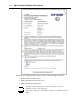
1-12 ADS Portable FlowShark Pulse Manual Delivery and Receipt Delivery of a Portable FlowShark Pulse measurement system typically includes the following components. Each item includes the part number for both the standard unit and the Ex version of the unit, when applicable.
Introduction 1-13 Product Warranty This section includes warranty information for the ADS Portable FlowShark Pulse. New Product Warranty All new products manufactured by ADS will be free from defects in material and workmanship for up to two (2) years following the date of shipment from ADS. During this warranty period, upon satisfactory proof of a defect, the product may be returned for repair or replacement, at ADS’s sole option.
1-14 ADS Portable FlowShark Pulse Manual THIS IS THE ONLY WARRANTY FOR ADS PRODUCTS. NO OTHER WARRANTY IS EXPRESSED OR IMPLIED, INCLUDING FITNESS FOR A PARTICULAR PURPOSE OR MERCHANTABILITY. PRODUCT REPAIR OR REPLACEMENT IS THE ONLY REMEDY. IN NO EVENT WILL ADS BE RESPONSIBLE FOR ANY DIRECT, INDIRECT, CONSEQUENTIAL, OR SPECIAL DAMAGES.
Introduction 1-15 Replacement Parts and Accessories ADS does not certify replacement parts or accessories that are not supplied by ADS. Installing and/or using parts or accessories supplied by other vendors could adversely affect the operation of the equipment. Therefore, users are responsible for all damages incurred as a result of using parts or accessories supplied by any manufacturer other than ADS.
CHAPTER 2 System Overview and Operation The Portable FlowShark Pulse is a portable monitoring system and data storage device designed for temporary flow measurement in slightly- to heavily-polluted flow of various compositions in partially-filled to full pipes of various shapes and dimensions. The system measures flow velocity by spatial allocation using ultrasonic pulses. Signal evaluation occurs through cross-correlation using a digital signal processor.
2-2 ADS Portable FlowShark Pulse Manual Portable FlowShark Pulse ADS primarily offers two versions of the Portable FlowShark Pulse: Portable unit powered by rechargeable battery pack (ADS p/n 5000-PPORT METER-4) Portable unit powered by rechargeable battery pack – Ex-certified (ADS p/n 5000-PPORT METER-10) The part number posted on a weatherproof label on the bottom of the enclosure identifies the version of the device.
System Overview and Operation 8 9 1 2 3 4 5 6 7 Part Description 1 Display 2 Keypad 3 Communications port (not applicable) 4 Combined mains adapter / battery charger port 5 Air-ultrasonic depth sensor port or external depth measurement 4-20 mA 6 Water-ultrasonic velocity / combination sensor or electronic box port 7 Multi-function port for connecting connection-box, active digital input, 0/4-20 mA input signal, or 0- to 10-volt voltage output and relay output 8 Battery compartment 9 Comp
2-4 ADS Portable FlowShark Pulse Manual D Air-Ultrasonic Depth Sensor I 0/4-20mA -External depth measurement -Data logging -Pump run time or -Event-based switchover Compact Flash Memory Card Portable FlowShark Pulse Connector-box D Water-Ultasonic Combination/Flow Velocity Sensor V 0-10 V -Sampler -Volume impulse -Limit contact or or -Flow velocity -Depth level -Flow volume -Water temperature -Analog input or or or or Possible combinations Use the connector-box only when connecting more tha
System Overview and Operation 2-5 Sensors The Portable FlowShark Pulse supports several sensor models, including waterultrasonic velocity/combination, pipe insertion, and air-ultrasonic sensors, that are available in different versions. Individual models may vary based on measurement capabilities, cable length, and unique construction. The part number identifying the sensor model is printed at both ends of the cable and on the bottom of the ground plate.
2-6 ADS Portable FlowShark Pulse Manual Water-Ultrasonic Velocity/Combination (Wedge) Sensors The Portable FlowShark Pulse uses a combination sensor that can simultaneously determine both flow velocity and flow depth or a standalone velocity sensor. A combination sensor may contain up to two 2 depth measurement devices: a waterultrasonic device and a hydrostatic (pressure) device.
System Overview and Operation Water-Ultrasonic Velocity/Combination Sensor 1 Connector with Spigot Nut (optional) 2 Sensor Cable 3 Sensor Body 4 Ground Plate 5 Cable Gland 6 Sensor for Flow Velocity Measurement 7 Sensor for Depth Measurement using Pressure Measurement Cell (optional) 8 Air Filter (optionally equipped with connector) Water-Ultrasonic Velocity/Combination Sensor with pressure depth option 2-7
2-8 ADS Portable FlowShark Pulse Manual 1 Ground Plate 2 Acoustic Coupling Layer 3 Temperature Sensor 4 Flow Velocity Sensor 5 Level (Depth)/Height Sensor (optional) 6 Electronics 7 Pressure Sensor (optional) 8 Pressure Measurement Duct (optional) 9 Cable Gland Water-Ultrasonic Combination Sensor with additional pressure measurement cell for installation at pipe bottom Air-Ultrasonic Depth Sensor ADS offers an air-ultrasonic depth sensor for the Portable FlowShark Pulse that uses horizo
System Overview and Operation 1 Plug with Spigot Nut (optional) 2 Sensor Cable 3 Sensor Body 4 Ground Plate 5 Cable Gland 6 Sensors for Depth Measurement using Air-Ultrasonic 2-9 Air-Ultrasonic Depth Sensor 4 2 1 1 Ground Plate 1 (optionally removable) 2 Ground Plate 2 (base plate) 3 Ground Plate 3 (spacer plate) 4 Cut-out for Pipe Mounting Plate Air-Ultrasonic Depth Sensor 3
2-10 ADS Portable FlowShark Pulse Manual Mini Sensors The Portable FlowShark Pulse also offers a "Mini" sensor family. This sensor family consists of the Electronic Box (EBM) (active electronics) and two passive sensors: the mini water-ultrasonic passive flow velocity sensor (below) used for measuring velocity and the mini air-ultrasonic passive depth sensor used for measuring level (i.e., depth).
System Overview and Operation Mini Air-Ultrasonic Depth Sensor 1 Ground Plate 2 Sensor for Depth Measurement using Air-Ultrasonic 3 Sensor Body 4 Cable Gland 5 Sensor Cable 6 Connector with Spigot Nut 7 Fastening Clamp for Ceiling Installation Mini Air-Ultrasonic Depth Sensor 1 Ground Plate 1 2 Ground Plate 2 (base plate) 3 Ground Plate 3 (spacer plate) 4 Cut-out for Pipe Mounting Plate Mini Air-Ultrasonic Depth Sensor 2-11
2-12 ADS Portable FlowShark Pulse Manual Electronic Box 1 Cable Connection to the Portable FlowShark Pulse 2 Cable Gland 3 Electronic Box Body 4 Connector for Mini Water-Ultrasonic Velocity Sensor 5 Connector for Mini Air-Ultrasonic Depth Sensor 6 Mounting Plate 7 Suspension Bracket Electronic Box (EBM) 1 Cable 2 Cable Gland 3 Ground Plate 4 Electronic Body 5 Port for Mini Water-Ultrasonic Velocity Sensor 6 Port for Mini Air-Ultrasonic Depth Sensor Electronic Box (EBM)
System Overview and Operation 1 Port for Mini Air-Ultrasonic Depth Sensor 2 Port for Mini Water-Ultrasonic Velocity Sensor 3 Not supported at this time 2-13 Overview of socket wiring for Electronic Box (EBM) Pipe Insertion Sensor The pipe insertion sensor primarily is used to measure flow velocity in closed pipes that remain full, eliminating the need for a depth measurement device.
2-14 ADS Portable FlowShark Pulse Manual 1 Sensor for Depth Measurement using Water-Ultrasonic (optional) 2 Sensor for Flow Velocity Measurement 3 Sensor Screw Joint (mobile) 4 Retaining Element 5 Sensor Body 6 Installation Help Screw M4 7 Cable Gland 8 Sensor Cable Pipe Insertion Sensor Flow Depth Measurement Based on the sensor model, the water-ultrasonic velocity/combination sensor may perform up to two types of depth measurement: Water-ultrasonic Hydrostatic fill level measuremen
System Overview and Operation 2-15 degree Centigrade). To ensure accurate depth measurements, all calculations must compensate for the flow temperature. Adding the sensor offset to the measured depth value (h1) determines the depth total (h). The sensor offset represents the distance from the bottom of the pipe to the sensor crystal position. The measured depth value represents the distance from the crystal to the flow surface.
2-16 ADS Portable FlowShark Pulse Manual reflection pattern. Several other factors also influence particle reflection and velocity profile measurement. Rotating particles may exhibit multiple shapes for reflection; particles may exit the measurement range before a subsequent measurement can occur; and new particles may enter into the measurement range.
CHAPTER 3 Installation Reading and following the installation instructions before initial start-up will help ensure success in flow measurement and device configuration. Do not power up the transmitter or initiate start-up until installation is complete and verified. If any problems occur during installation, connection, or configuration, please contact ADS Client Services at adssupportcenter@idexcorp.com or (877) 237-9585.
3-2 ADS Portable FlowShark Pulse Manual Transmitter Installation When selecting a mounting location for the transmitter, avoid locations exhibiting or influenced by the following: Direct sunlight (use weatherproof cover, if necessary) Heat-emitting objects (maximum ambient temperature of 122°F (50°C)) Objects generating strong electromagnetic fields (e.g.
Installation 3-3 Sensor Installation Please observe all regulations regarding safety at work and dangers due to explosive gases prior to the beginning of installation activities. Take the appropriate security measures as required. Choosing a Suitable Location for Sensor Installation Clear and stable hydraulic conditions are essential for obtaining accurate sensor measurements.
3-4 ADS Portable FlowShark Pulse Manual Sensors in Partially-Filled Pipes Sensor Adjustment: (left) proper installation in center that should yield reliable measurements; (right) faulty installation that will yield erroneous measurements Angle of the Curve in the Pipe v ≤ 3.3 feet per second (1 m/s) v > 3.3 feet per second (1 m/s) α ≤15° L ≥ min. 3 x DN L ≥ min. 5 x DN α ≤45° L ≥ min. 5 x DN L ≥ min. 10 x DN α ≤90° L ≥ min. 10 x DN L ≥ min.
Installation 3-5 Error! Undesirable flow conditions Sufficient distance to obtain steady flow (10 … 50 x diameter, depending on the application) Overflow pipes (flows immediately downstream from a weir wall) or drops create unstable flow conditions Error! Risk of silt build-up / sludge accumulation caused by negative slope Negative slope – risk of silt accumulation Error! Changes in slope = changes in flow profile Distance depending on slope and flow velocity reading l = minimum 20 x di
3-6 ADS Portable FlowShark Pulse Manual Error! Installed in draw-down, transitioning from flowing to falling Depth measurement may fail and velocity and depth measurement may be erroneous ? Critical measurement point, not recommended! Flow begins to fall (or sink) Distance l = min.
Installation 3-7 1 Waves forming on water surface behind sensor installed at bottom of pipe cause corresponding air-ultrasonic depth sensor to produce errors. 2 Good (consider installing 0.39 inches (10 mm) lower in low flow depth conditions) 3 Distance too far from edge of sensor bottom to maximum water level 4 Good.
3-8 ADS Portable FlowShark Pulse Manual Installation in manhole with depth levels >6 inches (150 mm) Error! Caused by vorticity and waves forming behind drop Choose another location or restore manhole Error caused by drop or changing slope
Installation 3-9 Sensors in Full Channels, Pipes, or Other Applications h ≤ 5% of DN L ≥ min. 3 x DN h > 5% of DN L ≥ min. 5 x DN h ≥ 30% of DN L ≥ min. 10 x DN Sensor position after change in profile For horizontal/level pipes, avoid mounting the sensors at the top or bottom of the pipe. Risk exists for sedimentation/silt or air bubbles resulting in measurement failure. ADS recommends mounting the sensor at a location -45° to +45° from the center horizontal axis of the pipe.
3-10 ADS Portable FlowShark Pulse Manual 1 Recommended range in almost horizontal position (sensor can be installed on the side) 2 Recommended range in vertical pipe 3 Not recommended due to partial filling/idling 4 Measuring impossible due to idling Comparison of installation locations When measuring in horizontal pipes, ADS recommends considering a slightly inclined section or an inverted siphon.
Installation 3-11 or Horizontal pipe with inverted siphon Always install shut-off valves and control fittings downstream of flow velocity sensors. Using shut-off valves and control fittings Never install sensors on vibrating pipes. This may result in erroneous readings.
3-12 ADS Portable FlowShark Pulse Manual Sensor Installation When installing the sensors, use only non-corrosive fastening materials and fasten the sensors both securely and tightly. Orient the velocity sensor so that the sloped side of the sensor is facing upstream against the direction of the flow. To avoid disturbances from electrical interference, do not locate sensor cables close (or parallel) to an engine (motor) or main power lines.
Installation 3-13 The bottom of the pipe must be completely flat (plane surface) for sensor installation. Otherwise, the sensor could experience damage or leakage, resulting in potentially irreparable damage to the electronic components. Do not bend the ground plate during installation or removal. Use only an appropriate screwdriver for sensor removal; do not use a pry bar, chisel, hammer, lever, crowbar, hammer drill, or similar tool. In addition, do not use excessive force to remove the sensor.
3-14 ADS Portable FlowShark Pulse Manual Installing a sensor with the integrated water-ultrasonic measurement capability Water-Ultrasonic Velocity/Combination Sensors with Integrated Pressure Measurement Cell To compensate for atmospheric pressure, sensors with integrated pressure measurement cells have an air hose located inside the cable. Do not buckle or seal this air hose or clamp the hose into hermetically sealed connection sockets without air pressure compensation.
Installation 3-15 Installing sensor with integrated pressure measurement cell (1 represents sedimentation (i.e., sand or sludge)) Air-Ultrasonic Depth Sensors Install an air-ultrasonic depth sensor using a pipe mounting system (RMS). To install the sensor using this mounting system, run the mounting sheet located in the pipe vertex (crown) through the cut-out in the air-ultrasonic depth sensor prior to final assembly.
3-16 ADS Portable FlowShark Pulse Manual Arranging the sensors in the pipe For a permanent installation, secure the air-ultrasonic depth sensor to the top of the pipe with 3 stainless steel screws (M5) or use the pipe mounting plate and attach the plate with appropriate anchors. To permanently secure the mini air-ultrasonic depth sensor, use the accompanying mounting shoe. Use screws of an appropriate length to ensure safety and durability under all operational conditions.
Installation 3-17 Proper installation (left) and improper installation (right) Installation susceptible to buildup of debris (left) and improper installation (right) Sensor properly facing flow direction (left) and sensor facing the wrong direction (right) Please note the following for installation in pipes: • Weld on the 1.5-inch nozzle at a 90° angle. • Position the sensor so that the bevelled edge is facing upstream. The sensor block must be welded to steel and stainless steel 1.
3-18 ADS Portable FlowShark Pulse Manual accommodate the sensor shaft. ADS recommends using a 1.5-inch (38-mm) diameter steel rod to test for interference to ensure the sensor shaft will fit into the pipe. For assistance when installing the sensor taps or fittings, please contact the pipe manufacturer or a professional pipe fitter.
Installation 3-19 1 Gasket ring 2 Thread 3 Inner cone 4 Inner thread of spigot nut 5 O-ring inside of sensor screw connections Using grease on the cutting ring screw joint Prior to installation, grease the screw joint at all points shown in the image above. Install the sensor according to DIN 3859-2. Screw the screw joint into the welding nozzle, ball valve, or the nozzle of the tapping saddle using a pipe wrench or an open-end wrench (width across flats: 2.2 inches (55 mm)).
3-20 ADS Portable FlowShark Pulse Manual 1 Welding nozzle 2 Stop ball valve 3 Sensor screw connection 4 Sensor retaining element 5 Installation aid (M4 screw) Components of pipe insertion sensor mounting Risk of accident! Increased pressure or pressure surges may cause unsecured flow velocity sensors to become unscrewed and, therefore, dangerous to people as well as parts of the facility! Ejected sensors may cause the medium to flow out of the screw connection and flood the facility! The sensor
Installation 3-21 A Sensor screw connection (old version) B New sensor screw connection 1 Slot for O-ring 2 Extended thread run-out 3 Hexagon length reduced from 9 mm to 6 mm Comparison between both screw connections ADS cannot guarantee the rear clamp element will safely sit on the screw connection if the sensor retaining element is used with an older sensor screw connection! To ensure safe clamping, degrease the rear area of the pipe sensor as well as the clamping area (half-round milling groov
3-22 ADS Portable FlowShark Pulse Manual 1 Upper front clamp element (1x) 2 Lower front clamp element (1x) 3 Upper rear clamp element (1x) 4 Lower rear clamp element (1x) 5 Allen head screw M5 (2x) 6 Allen head screw M4 (2x) 7 Welded headless screw (as an additional clamp lock) 8 Allen head screw M5 (2x) 9 Allen key – 1 x 2.
Installation 3-23 Greasing the sensor screw connection 2. Screw the sensor screw connection into the welded nozzle or the stop ball valve. Securing the sensor screw connection to the stop ball valve 3. Place the pipe insertion sensor into the proper position.
3-24 ADS Portable FlowShark Pulse Manual Properly positioning the sensor 4. Fasten the sensor by gently tightening the union nut manually (plus ½ turn). Fastening the sensor 5. Screw the upper and lower front clamp elements together behind the spigot nut of the sensor screw connection using two M4 Allen® head screws.
Installation 3-25 Attaching the lower front clamp element 6. Screw the upper rear clamp element to the upper front clamp element using both M5 Allen head screws. Connecting the upper rear and upper front clamp element 7. Subsequently attach the lower rear clamp element to the upper rear clamp element using the two remaining M5 Allen head screws. Apply a minimum torque of 6 Nm to tighten the screws to ensure the connection is secure.
3-26 ADS Portable FlowShark Pulse Manual 8. Verify the tightness of the entire screw joint. If leaks develop during this process, make sure the respective screw joints are properly tightened or shut down the entire facility (if necessary) and replace the damaged gaskets, Teflon tapes, and other materials. Attaching the final clamp element 9. The sensor retaining element allows you to reposition the sensor in the proper location following maintenance or control measures.
Installation 3-27 Removing the sensor (maintenance/control) 11. Clean or inspect the sensor as necessary. You can reinsert the sensor into the screw connection once again as soon as the cutting ring has been replaced. Use the rear clamp elements left on the sensor body as a detent or positioning aid. 12. Tighten the spigot nut and M5 Allen head screws again.
3-28 ADS Portable FlowShark Pulse Manual 1 Stainless steel sheet/cable cover 2 Cable 3 Cable 4 Permanent, elastic material Suggested cable layout Do not run the cable loosely, uncovered, or across the medium. This could lead to a build-up of debris and/or cause the sensor or the cable to pull apart. Cable layout (1 represents the protective cover) Do not bend the standard signal cable in more than a 4-inch (10cm) radius. Bending it into a smaller radius could break the cable.
Installation 3-29 Sensor Connection Water-Ultrasonic Velocity/Combination Sensor, Air-Ultrasonic Depth Sensor, and Electronic Box Water-ultrasonic velocity/combination sensors, air-ultrasonic depth sensors, and electronic boxes (EBM) are equipped with cable-end connectors for connection to the corresponding ports on the Portable FlowShark Pulse transmitter.
3-30 ADS Portable FlowShark Pulse Manual When using the water-ultrasonic velocity/combination sensor with the integrated pressure cell, do not operate the transmitter without the filter installed. Removing the filter connector from the sensor connector will automatically lock the filter connector. While a locked connector prevents water from entering the sensor, it also disrupts air pressure compensation. This inhibits the pressure cell from accurately measure depth.
Installation 3-31 Input/Output Application Cable Description Analog Input 32.8-foot (10-m) connection cable, Portable FlowShark Pulse – analog input (one end with connector for multifunctional port, other end with open cable end) Analog Output 32.8-foot (10-m) connection cable, Portable FlowShark Pulse – analog output (one end with connector for multifunctional port, other end with open cable end) Digital Input 32.
3-32 ADS Portable FlowShark Pulse Manual Connector Box A connection box (ADS part number 5000-PULSE-CONN-BOX) is available through ADS for connecting several devices to the Portable FlowShark Pulse simultaneously. 1 Pre-drilled holes for M4 screws for fastening enclosure 2 Pressure compensation element DAE 3 M20 x 1.5 cable gland 4 M16 x 1.5 dummy plug 5 3.
Installation 3-33 Electronic Box (EBM) Seal unused connection sockets on the Type EBM Electronic Box watertight by fastening the screw cover on each socket prior to installation. Otherwise, ADS cannot guarantee the protection of the entire unit. The ADS warranty does not cover damages resulting from uncovered connection ports. ADS offers, at an additional cost, covers to replace those damaged or lost due to the use of force.
3-34 ADS Portable FlowShark Pulse Manual Accessories and Installation Aids Pipe Mounting System The pipe mounting system is an installation resource for water-ultrasonic velocity/combination sensors, mini water-ultrasonic velocity sensors, air-ultrasonic depth sensors, and mini air-ultrasonic depth sensors primarily used for portable applications.
Installation 3-35 RMS 2 Pipe Mounting System RMS 2 Determine the appropriate parts required based on the figure below, the following chart, and the existing pipe diameter.
3-36 ADS Portable FlowShark Pulse Manual I.D.
Installation 3-37 Snap the water-ultrasonic sensor onto the base plate with the slotted holes located toward the rear of the sensor. Left Center Right Place the sensor with the cutouts (slotted holes) onto the base plate. Slide back the sensor until completely in place. Make sure the sensor locks securely and flush with the base plate. Connecting the sensor to the base plate Rotate the clamp handle of the scissors jack clockwise until the scissors are closed.
3-38 ADS Portable FlowShark Pulse Manual When using the air-ultrasonic depth and water-ultrasonic sensors simultaneously, use the support plate (ADS part number 5000-PPORT-PIPEINST-RMS2). In this configuration, the water-ultrasonic sensor mounts to the base plate with the slotted holes at the front of the sensor. The support plate ensures proper cable layout and placement of the water-ultrasonic sensor behind (downstream from) the air-ultrasonic sensor.
Installation 3-39 RMS 3 1 Fastening clip 2 Base plate BST 3 Extension sheet V5 4 Extension sheet V10 5 Scissors jack Components included in the pipe mounting system 3 Inside Diameter BST Base Plate SPV Scissors Jack V5 Extension Plate V10 Extension Plate 160 mm X inner hole X X 200 mm (8 inches) X inner hole X 250 mm (10 inches) X inner hole X X X 300 mm (12 inches) X outer hole X X X X Table of mounting sheets for different pipe diameters During assembly, always locate th
3-40 ADS Portable FlowShark Pulse Manual Left Assemble the base plate and extension sheet Center Right Insert the pins into the holes Lock the pins using the fastening clip (clip must sit flush against the mounting plate facing the oncoming flow) Assembling the mounting plate Left Center Right Place the sensor with the cutouts (slotted holes) onto the base plate. Slide back the sensor until it is completely in place. Make sure the sensor locks securely and flush with the base plate.
Installation 3-41 Left Connect the scissors jack to both sides of the final plate using the fastening clip. Right Turn the scissors jack clockwise all the way until it is closed before installing the mounting system into the pipe. Assembling the RMS 3 pipe mounting system with the scissors jack Rotate the clamp handle of the scissors jack clockwise all the way until the scissors are closed.
3-42 ADS Portable FlowShark Pulse Manual 1 Scissors jack 2 Mini water-ultrasonic velocity sensor 3 Mini air-ultrasonic depth sensor Fastening the sensor on the pipe mounting system RMS 3 RMS 3 installed with mini water-ultrasonic velocity sensor and mini air-ultrasonic depth sensor
Installation 3-43 Sensor Cover High velocity flow with a substantial amount of grit or stone poses a significant risk of damage to the sensor body. Therefore, ADS offers a sensor cover (ADS p/n 5000PULSE-PROTECT-SENS) to protect the sensor against the impact of large objects and to limit mechanical stress to the sensor body. However, if the cover is used in slower flows, a higher potential for build-up exists. Therefore, it may require more frequent cleaning.
3-44 ADS Portable FlowShark Pulse Manual Pipe Profiler The Pipe Profiler is a pipe measuring section that serves as an extension of the Portable FlowShark Pulse measurement system. This flexible measurement system ensures accurate flow measurement even under difficult conditions such as low discharge volumes or poor hydraulic conditions.
Installation 3-45 Safety filling valve As with other field activities, mounting and installation of a Pipe Profiler requires two field crew members. The following images corresponding to pipe profiler installation are for illustration purposes only. Please observe all applicable safety procedures regarding confined space entry to protect human health and prevent injuries.
3-46 ADS Portable FlowShark Pulse Manual Installation requires a 2-person crew Install the pipe profiler in the following way: 1. Lower the pipe profiler into the manhole on a chain. 2. Be careful to avoid straining the cable or air hose. Lowering the pipe profiler into the manhole by a chain 3. Insert and adjust the pipe profiler in the pipe so that the opening of the pressure pipe faces upwards.
Installation 3-47 4. Add a little pressure into the balloon using the safety valve. Widen the balloon wide enough to seat the pipe profiler against the pipe walls first. Adjust the profiler in a vertical position. Inserting and adjusting the pipe profiler 5. Exit the manhole before completely inflating the balloon! 6. Fill up the balloon completely to a pressure of 21.8 psi (1.5 bars). Filling the balloon to 21.
3-48 ADS Portable FlowShark Pulse Manual Do not allow anyone into the manhole during balloon inflation to 21.8 psi (1.5 bars)! Injury can occur from flying parts or the blast wave resulting from an exploding balloon (e.g.
Installation 3-49 An air vent plug is attached to the air hose on the end connected to the compressor. This plug is required for dismantling the profiler. Dismantle the profiler in the following way: Prior to dismantling the profiler, prevent it from floating away using the chain. For example, consider tying the unit to a manhole rung.
CHAPTER 4 Power The Portable FlowShark Pulse comes standard with a rechargeable, lead gel battery pack for power. This battery pack offers an extensive battery life for taking measurements long-term. The unit also can receive power directly from a mains (100-240 V AC) power source.
4-2 ADS Portable FlowShark Pulse Manual Rechargeable Battery Pack The rechargeable lead gel battery pack resides in a padded battery compartment in the Portable FlowShark Pulse. This compartment is accessible from the inside of the unit through a cover/lid located to the right of the display that is secured with four screws. Upon delivery, the battery pack will arrive fully charged.
Power 4-3 Always disconnect the battery charger/power adapter from the mains power source prior to connecting it to or disconnecting it from the battery pack. The battery charger/power adapter has a built-in LED to indicate the charging status.
4-4 ADS Portable FlowShark Pulse Manual Recharge the battery pack before each use of the Portable FlowShark Pulse. Remove battery packs from units that are not in use, and store them in a dry, frost-free location. Recharge them every two months (when not in use) to maintain capacity. Make sure the battery compartment remains locked firmly during system operation. Discard used rechargeable battery packs according to state and local regulations regarding battery disposal.
Power 4-5 Mains Power To power the Portable FlowShark Pulse from a mains (100 – 240 V AC) power source, attach the connector from the mains adapter/battery charger cable to the corresponding port on the unit. Do not remove the rechargeable lead gel battery pack from the unit during mains operation. Battery charging occurs simultaneously with mains operation.
CHAPTER 5 Initial Startup After installing and connecting the Portable FlowShark Pulse transmitter and sensors and charging the battery pack/providing mains power to the unit, you can initiate system startup and begin setting the system parameters through the transmitter’s user interface. ADS strongly recommends using this manual to understand how to properly program the Portable FlowShark Pulse via the display and keyboard.
5-2 ADS Portable FlowShark Pulse Manual Keypad The Portable FlowShark Pulse has an 18-button keypad for setting parameters and inputting other data.
Initial Startup 5-3 Display The Portable FlowShark Pulse has a large, backlit graphic display with a 128- x 128pixel resolution.
5-4 ADS Portable FlowShark Pulse Manual The top of the display provides five basic menus for selection: RUN This menu represents the standard mode of operation. In addition to indicating the name of the measurement location, this menu allows you to view time, flow rate, flow depth, average flow velocity (as well as flow velocity distribution), daily totals, and error messages. It also includes a function that enables you to record flow volume, flow depth, and average flow velocity data.
Initial Startup 5-5 Operation Basics The Portable FlowShark Pulse has a user-friendly interface and is completely menu driven. Use the control keys to navigate through the menus (refer to Chapter 6, Parameter Settings). Use these buttons to move among the main menus. Use these buttons to scroll within the main menus. Use this button to enter a submenu (or the input field) selected using the right/left arrow keys. This button also exists for confirming data entries.
5-6 ADS Portable FlowShark Pulse Manual Shut-off the Portable FlowShark Pulse
Initial Startup 5-7 Measurement and Display Functions After the system parameters are set, the Portable FlowShark Pulse will perform a complete system reset and then begin taking measurements based on the designated interval. The time required for taking measurements within each interval is based on the flow and hydraulic conditions. The number of storage events per hour is based on the number of intervals designated within a full hour.
5-8 ADS Portable FlowShark Pulse Manual t1 = Programming time (any period) t2 = System reset and restart (approximately 7 seconds) t3 = Cycle time (constant; will change only for designated events; 1 minute…60 minutes) t4 = Measurement duration, depending on hydraulic and physical conditions, will reset each time (5 seconds…40 seconds) Measurement and display functions following parameter modification Display Functions Outside Memory Mode When initially setting up the Portable FlowShark Pulse
CHAPTER 6 Parameter Settings After installing the system (refer to Chapter 3, Installation) and activating the power supply, set the configuration parameters for the system to ensure reliable device operation.
6-2 ADS Portable FlowShark Pulse Manual Basics for Setting Parameters The unit’s protection is guaranteed only when the enclosure lid is closed and locked securely using both locks. Therefore, always verify that the lid is locked safely using both snap locks after setting the parameters, before initiating data logging activities, and after verifying the initial readings.
Parameter Settings 6-3 Language selection Select the desired language using the arrow keys, and then press Enter to confirm. Initiate a system reset prior to each initial startup to reset the unit to the factory default settings. This helps prevent errors that can occur based on improper settings. During a full reset, the unit loses any custom parameters and restores the factory default parameters.
6-4 ADS Portable FlowShark Pulse Manual Start Assistant The Start Assistant displays only at initial start-up or after resetting the system, restarting a deactivated unit, or reconnecting the battery. It provides a quick start-up procedure that guides you step-by-step through setting the primary parameters. Select ENTER to go to the next step. This chapter offers detailed descriptions of all the parameters. Select NO to continue to the display menu without using the start assistant.
Parameter Settings 6-5 Selecting medium pollution Name ADS recommends managing and defining location names based on the names referenced in the respective documentation. Location names may contain up to 21 letters. The method used for setting the name is similar to the method used for entering text in a cell phone (e.g., SMS).
6-6 ADS Portable FlowShark Pulse Manual Selecting the channel shape and channel geometry When you select NPP as the channel profile, the unit will automatically use optimized settings for measurements in full pipes in the background. Sensor Type Scroll through the sensor type(s) using the up and down arrow keys. Press the ALT key to select each respective sensor, and then confirm by selecting ENTER.
Parameter Settings 1 Top layer sensor 2 Threshold level between the middle and top layers 3 Middle layer sensor 4 Threshold level between the middle and bottom layers 5 Bottom layer sensor 6-7 Subdividing level (depth) sensors Mounting Offset Selecting Water-US int. and Pressure int. sets this value to 0 mm by default. The bottom edge of the ground plate (channel bottom) serves as the reference point.
6-8 ADS Portable FlowShark Pulse Manual Storage Mode Set the storage cycle for the compact flash card at a rate from 1 to 60 minutes. Changing the storage cycle Save New Values The unit will prompt you to either save all the values or ignore the selections before finishing the start assistant. Reject all values by selecting NO at the end of the parameter setting procedure. You can browse through all the values again in the Start Assistant by selecting the BACK function.
Parameter Settings 6-9 Operation Mode (RUN) This menu displays when the unit is in standard operating mode. The parameters contained in the following submenus are not essential for parameter setup: Selecting the standard operating mode RUN: Standard This screen displays basic information including the measurement location name and the current time (alternately displays median temperature), flow rate, average velocity, flow depth (level), and flow volume.
6-10 ADS Portable FlowShark Pulse Manual 1 Measurement window 2 Velocity value 3 Velocity measurement window number 4 Depth (level) value 5 Depth (level) measurement window number 6 Maximum velocity 7 Maximum height Flow velocity distribution Very good profile, area free of backwater Good profile, strongly tending to backwater formation or very high flow velocity Poor profile Unsuitable profile Suitable profile Flow velocity profiles RUN: Day Values This menu indicates the day total val
Parameter Settings 6-11 Day total values menu INFO This menu contains the total flow values from the past 90 days, provided the transmitter has operated without interruption for the past 90 days. If an interruption occurs, it displays the flow totals for the uninterrupted days of operation. Reset the total to 0 by pressing the ALT key. This reset will not impact the totalizer. Cycle The Portable FlowShark Pulse typically calculates flow totals at midnight (00:00 h).
6-12 ADS Portable FlowShark Pulse Manual Erasing day values from memory Confirming the clearing of the memory RUN: Errors This screen allows you to monitor any interruptions in unit function. The unit saves and organizes errors by the type of error and the date and time at which the error occurred. The ALT key deletes error messages one at a time, from the latest to the oldest. Deleting an error message is equivalent to confirming the error.
Parameter Settings 6-13 The period over which the measurements have been taken displays at the bottom of the screen. Use the left/right arrow keys to select the desired period you want to view (up to 14 days). 1 Memory interval 2 Trend graph 3 Maximum value Example of trend graph Resetting the system clears the content in the internal memory and deletes all graphic value trends previously saved to memory.
6-14 ADS Portable FlowShark Pulse Manual Display Menu (EXTRA) This menu allows you to modify settings, such as the standard screen, units, language, and display. The EXTRA menu contains the following submenus: Figure 8-13 Extra submenus EXTRA: Units From this menu, you can select the unit system in which readings will display. Select from among the metric system (liter, cubic meters, cm/s, etc.), English (UK) system (ft, in, gal/s, etc.), and English (US) system (fps, mgd, etc.).
Parameter Settings The and buttons modify settings at 5 percent increments; the buttons modify settings at 1 percent increments. 6-15 and EXTRA: Set Time To perform various control and memory functions, the unit includes an internal system clock for saving dates corresponding to years, weekdays, and weeks. When necessary, you can modify clock date and time. First, select the Info menu option.
6-16 ADS Portable FlowShark Pulse Manual Parameter Menu (PAR) Parameter submenu This is the most comprehensive and critical menu involved in setting Portable FlowShark Pulse parameters. While you can modify many different parameters, the system typically only requires you to set the following parameters: Location name Pipe shape Pipe dimensions Sensor types Storage mode All other functions correspond to unique circumstances or applications.
Parameter Settings 6-17 Due to the limited area for display, the entire menu cannot display on the screen. The black scroll bar to the right of the menu options indicates that additional options are available on the menu. Use the up and down arrow keys to scroll through the menu. Measurement Place Name ADS recommends managing and designating names based on the names used in the associated documentation. A name may contain up to 21 characters.
6-18 ADS Portable FlowShark Pulse Manual Rectangle U-Profile Trapezoid A = f (h, w) 2r Egg (height-to-width ratio = 1:1) NPP (Pipe Profiler) Special profiles, such as Q = f (h), A= f(h), three-part profiles, and two-part profiles also are available. Selecting the shape of the pipe The unit saves the selected profile. The next step requires entering the channel dimensions of the profile.
Parameter Settings 6-19 Example of selecting NPP Setting the channel geometry in pipe profiles The unit subsequently displays the selected profile and channel dimensions in programming mode. Selected profile Channel Geometry Enter the corresponding pipe dimensions based on the previously selected profile. Please note the units of measure in which the values are displayed.
6-20 ADS Portable FlowShark Pulse Manual Table of custom shape breakpoints To define the zero point for the pipe, begin by entering 0 – 0 for breakpoint 1. Enter the subsequent segments based on the height and width/area. Distances may vary among individual depth segments. Please note that it is not necessary to use all 32 segments. The Portable FlowShark Pulse will interpolate between the missing segments.
Parameter Settings 6-21 Example of setting custom profiles Choosing the 3-part profile displays the following setting options: • Bottom Area: U-Profile • Center Area: Custom Profile • Top Area: Pipe The center area can be custom designed. Dividing the profile into three zones The following screen provides an example of a special profile.
6-22 ADS Portable FlowShark Pulse Manual Configuring individual pipe sections is necessary only for special or very unusual profiles with convex tops and requires comprehensive knowledge and experience in operating the Portable FlowShark Pulse. To ensure proper configuration and/or to obtain assistance in setting up these parameters, please contact ADS. Sludge Level This parameter represents the depth of the sludge that has accumulated at the bottom of a pipe.
Parameter Settings 6-23 Submenu for level measurement Additional programming may be required depending on the sensor type selected. Selecting the wrong sensor will result in erroneous measurements. This menu allows you to define the parameters corresponding to depth measurement. The start screen and the available parameters may vary based on the sensor type selected. First, scroll to the sensor type using the up and down arrow keys. Select or deselect sensors using the ALT key.
6-24 ADS Portable FlowShark Pulse Manual This sensor allows you to measure low flow levels (e.g., for detecting infiltration). It must be installed in the center of the pipe crown (+/- 2°) and parallel to the water surface. Sensor type 1: Air-Ultrasonic Option 2: Water-Ultrasonic This option involves level (i.e., depth) measurement using the water-ultrasonic combination sensor and height measurement via water-ultrasonic from the bottom up.
Parameter Settings 6-25 Option 3: Two-Wire Sensor This option involves depth measurement using an external 2-wire sensor (not supplied by ADS). The system calculates flow rate exclusively using Q = f(h) without an additional velocity sensor. However, the velocity sensor may be used in conjunction with this sensor. Sensor type 3: Two-Wire Sensor Option 4: Fixed Value This option is recommended for applications involving pipes and channels that remain full (e.g.
6-26 ADS Portable FlowShark Pulse Manual The remaining options involve combinations of the preceding options. These may be necessary when structural conditions prohibit a single sensor from adequately addressing the entire measurement range at a location. Sensor Combination 1: Air-Ultrasonic and Pressure ADS recommends this option for measuring flow at a location that can experience flows ranging from 0 inches to surcharge conditions.
Parameter Settings 6-27 P Water-Ultrasonic and Pressure Sensor Combination: Air-Ultrasonic and Water-Ultrasonic ADS recommends this option for measuring flow at a location that can experience flows from 0 mm up to 80 percent capacity. The water-ultrasonic depth sensor measures depths from approximately 2 inches and above; the air-ultrasonic depth sensor measures the lower depths. The water-ultrasonic combination sensor must be installed at the bottom of the pipe in the center.
6-28 ADS Portable FlowShark Pulse Manual measures the medium range, and the air-ultrasonic depth sensor measures the low range. The water-ultrasonic combination sensor must be installed at the bottom of the pipe in the center. P Air-Ultrasonic, Water-Ultrasonic, and Pressure Sensor Combination: Pressure, Water-Ultrasonic, and Two-Wire Sensor ADS recommends this option for applications exhibiting the same conditions as described with the previous air-ultrasonic, water-ultrasonic, and pressure combination.
Parameter Settings Height h Mounting height water-US int + pressure int Height H Mounting height water-US NIVUS 6-29 Mounting offset of level (depth) sensors After modifying the mounting height of the pressure or waterultrasonic depth sensors, you must adjust the mounting height in the PAR > Flow velocity menu by the same value! Select Layers This parameter will display only when you have selected a sensor combination. The Portable FlowShark Pulse automatically aligns the sensors to partial layers.
6-30 ADS Portable FlowShark Pulse Manual Overview of depth sensors Scale This option allows you to enter a measurement offset, measurement range, and time delay or the fixed depth level corresponding to the input signal, based on the selected sensor type. Time Delay This parameter represents the amount of time required, once the Portable FlowShark Pulse has been turned on, for the external sensors to stabilize for measurement.
Parameter Settings 6-31 PAR: Velocity The Portable FlowShark Pulse supports a flow velocity sensor housed in a waterultrasonic combination sensor with integrated depth measurement or as a standalone water-ultrasonic velocity sensor. Sensor settings Choosing sensor type displays the following screen: Selecting the sensor type Sensor Type Choose the wedge (combination) or pipe insertion sensor and float (measurement from above) or Pos-alpha (positioned at any angle up to vertical) using the ALT key.
6-32 ADS Portable FlowShark Pulse Manual height h Mounting height of the sensor body angle b° Sensor installation angle diverging from vertical w Maximum possible distance between the sensor and an obstruction (e.g., the opposite wall in a horizontal installation) This dimension must be calculated and entered by the user. The Portable FlowShark Pulse will determine this length (w) automatically once the unit measures a shorter distance to the flow surface, based on the depth level.
Parameter Settings 6-33 The analog output on the Portable FlowShark Pulse is a 0 – 10 voltage output. Designate the functions for the analog output through this menu. Name (optional – for internal use only) To enter the name, follow the same procedure used for PAR > Measurement Place > Name.
6-34 ADS Portable FlowShark Pulse Manual Completed screen with correct settings Example: The measurement location can tend to experience backwater conditions and, therefore, negative values must be recorded. The analog output signal for this scenario must be set to floating. As a result, configure the measurement span so that the unit will output a V signal for flow = 0 reading in the middle of the measurement span. Example: 0 V = -100 l/s (-2.28 mgd) 10 V = 100 l/s (2.
Parameter Settings 6-35 Function Assign one of the following functions to the relay that corresponds to a specific channel number: Inactive No signals from digital output Flowrate Output Energizes the relay if the flow exceeds a designated threshold and de-energizes it if the flow falls below a second designated threshold Level Output Energizes the relay if depth exceeds a designated threshold and de-energizes it if depth levels fall below a second designated threshold Velocity Output Energ
6-36 ADS Portable FlowShark Pulse Manual Relay trigger level settings The switching behavior depends on whether the switch-on setting is set higher or lower than the switch-off setting: threshold behaviour (ON > OFF) or as an in-range alarm (ON < OFF). Pos-Total Impulse This menu displays only when the Pos-Total Impulse function is selected. Setting impulse parameters Duration s Enter the duration for the impulse and adjust the value based on the selected impulse counter.
Parameter Settings 6-37 Sampling This menu displays only when the water test function is enabled. Relay settings for sampling Duration (seconds) Enter the duration for the impulse. Modify this setting based on the sampler in use. Volume [mgal] Enter the volume at which to close the contact for the designated duration. Level [ft] Enter the depth beyond which to close the contact. This parameter serves to protect the sampler from drawing in air.
6-38 ADS Portable FlowShark Pulse Manual Executing a general reset Selecting Yes will erase the flash memory. Saving new values after system reset Before exiting the menu, the unit seeks confirmation on whether to save new values. Selecting Yes will reset the Portable FlowShark Pulse to the default parameter settings. The default settings will be restored and all customer modifications will be eliminated (general system reset).
Parameter Settings 6-39 Damping, Example 2: Damping 30 seconds, jump from 80 l/s to 100 l/s (=20 %) – unit requires 6 seconds to run from 80 l/s to 100 l/s. Stability Enter the amount of time to allow the readings to stabilize when measurement dropouts occur due to conditions such as hydraulic interference. The damping and stability parameters are not applicable when the unit is in active memory mode.
6-40 ADS Portable FlowShark Pulse Manual Memory card slot on transmitter (left) and memory card (right) Due to the limited number of storage cycles on the memory card (approximately 100,000 writing events) and for its protection, the Portable FlowShark Pulse initially stores measurement data to internal memory. The unit saves this data to the card on an hourly basis, pre-set by the internal system time.
Parameter Settings 6-41 Periodic This option provides cyclical storage of flow data and peripheral input signals. Delta Event The Portable FlowShark Pulse can toggle between two logging options: Switchover Operation This involves initiating the recording of readings immediately after a depth threshold is exceeded or a specific impulse from the digital input is received. Continuous operation This involves continuously recording readings similar to using a permanent flow meter.
6-42 ADS Portable FlowShark Pulse Manual Periodic interval This parameter exists for selecting the interval at which to save or record data. Choose a storage interval from 1 minute to 1 hour. The available intervals include 1, 2, 3, 4, 5, 6, 10, 15, 20, 30, and 60 minutes. Event Interval This parameter is available when the event mode is enabled and exists for defining the interval at which the unit stores data during an event. Designate the storage interval from 1 minute to 1 hour.
Parameter Settings 6-43 . Selecting the unit system for the storage mode Selecting the measurement value in storage mode Selecting the units of measure for the measurement in storage mode Wakeup level Define the depth level (threshold) at which to transition from storing data on a periodic interval to an event interval. Wakeup level at which to switch to storing data at an event interval Format of numbers Choose whether to save data with commas or dots to represent decimal points.
6-44 ADS Portable FlowShark Pulse Manual Data Structure on the Memory Card Main Directory FLASH and PARA Subfolders Data structure on the memory card DATA This folder represents the location in which the file containing the day totals (TOTAL.TXT) is stored. Save the day totals by selecting I/O > Memory card > Day values. . FLASH This folder represents the location in which the backup file is saved (To execute the backup, select I/0 > Memory Card > Save backup).
Parameter Settings 6-45 name of measurement place.TXT This is the file in which all of the flow data readings are stored. It is saved under the name of the measurement location. NIVIDENT.TXT The name of this text (.txt) file reflects the name of the measurement location. If the location name saved to the memory card is not consistent with the name of the measurement location saved to the Portable FlowShark Pulse, the unit will prompt you to format the card.
6-46 ADS Portable FlowShark Pulse Manual Port (socket) selection for independent readings Port Socket 1 Input via multifunctional port 1 (2-wire signal, input is passive) Socket 3 Input via multifunctional port 3 (2-wire signal, powered via the Portable FlowShark Pulse) Measurement Span Use the ALT key to modify the measurement span from 1-20 mA to 4-20 mA. Measurement span of independent readings Set the necessary parameters after selecting the measurement span.
Parameter Settings 6-47 Units of independent readings Linearization Define the analog input span from this menu location. The Portable FlowShark Pulse allows you to modify the weighting of the analog input using a 16-digit (maximum) breakpoint table. When properly used, this feature can introduce some beneficial options for setting parameters.
6-48 ADS Portable FlowShark Pulse Manual Signal Input/Output Menu (I/O) This menu includes several submenus that enable you to access and to verify the sensors as well as control signal inputs and outputs. It also displays various readings and measurements, including current inputs and outputs, relay conditions, echo profiles, and individual velocities. However, it does not enable you to modify signals or settings, such as offsets, adjustments, or simulations.
Parameter Settings 6-49 Calculated Values This menu allows you to view the values calculated from the analog input signal selected previously in the unit. Calculated values I/O: Digital Inputs This menu enables you to view digital input values routed to the transmitter input clamps. It indicates either OFF or ON. Digital input values I/O: Analog Outputs Analog input values This menu allows you to view the calculated voltage that will be sent to the analog converter.
6-50 ADS Portable FlowShark Pulse Manual I/O: Sensors This menu and the associated submenus allow you to view and assess the sensor status and operational conditions. It provides information on the measurement location quality, echo signal quality, and many other parameters. I/O submenu, V-sensor V-Sensor Selecting this option displays a 2-page table that includes all the individual velocity readings and the heights of the corresponding measurement windows.
Parameter Settings 1 Level 2 Level water-us 3 Level pressure internal 4 Level air-us 6-51 Example: Menu with water-ultrasonic, pressure, and air-ultrasonic 1 Level 2 Level water-us 3 Level pressure internal 4 Level 2-wire probe Example 2: Menu with water-ultrasonic, pressure, and 2-wire sensor The sensor types display in this way only when 1 or 2 types have been selected.
6-52 ADS Portable FlowShark Pulse Manual Echo profile for depth measurement The graphic displayed above enables service personnel to assess the echo signal within the acoustical range of measurement. Ideally, the initial peak (representing echoes from flow/air interface) will be very narrow, steep, and high. The remaining peaks (representing double and multiple reflections caused by the signal echoing back and forth between the flow/air and flow/pipe interfaces) will be lower and wider.
Parameter Settings 6-53 I/O: Memory Card This menu enables you to view information on the memory card. Memory card options Card info menu This information is accessible only when the memory card is installed in the unit. To view the remaining storage capacity (based on time) on the card, it must be installed in the unit for at least one hour. You can execute the process of formatting the card through the Memory Card menu. Formatting the card Only use memory cards purchased through ADS.
6-54 ADS Portable FlowShark Pulse Manual Select store parameter to save the parameters to the memory card. This procedure takes approximately 30 seconds; a progress bar displays for tracking purposes. Once it is successful and complete, the display will provide notification and the memory card menu will appear. Saving parameters to the memory card The load parameters menu option displays all the program files available on the memory card.
Parameter Settings 6-55 Saving day totals I/O: System This menu enables you to retrieve current battery information. It also recalculates the capacity of the rechargeable battery following replacement. System menu Selecting YES resets the capacity to 100 percent and calculates the projected battery life for the new battery. The bar graph indicates the percentage of battery life that remains. based on the maximum capacity of the battery and the consumption of power.
6-56 ADS Portable FlowShark Pulse Manual 1 Current date and time 2 Number of hours of operation remaining in the unit for taking measurements. This reading does not include periods on standby. 3 Consumption of power (in ampere hours) during operation 4 Condition of digital input 5 Current power consumption and battery voltage. Do not allow the battery voltage to fall below 11.5 volts before replacing or recharging the battery.
Parameter Settings 6-57 Calibration and Calculation Menu (CAL) This menu enables you to adjust the depth sensors and the settings for flow velocity measurement. It also allows you to generate simulations involving relay switching events, analog outputs, and flow. Menu selection CAL: Level This submenu enables you to calibrate the depth sensors for various purposes, such as adjusting the depth offset to compensate for structural conditions.
6-58 ADS Portable FlowShark Pulse Manual Pressing the Enter ( ) key after confirming the reference value displays an overview screen showing all the active depth sensors and a comparison between the previous (existing) and new offsets. The Portable FlowShark Pulse will display an error message if the difference between the offsets is too significant and, therefore, reject the new offset. If this occurs, repeat the calibration procedure and, if necessary, verify the sensor installation at the location.
Parameter Settings 6-59 min. + max. value This parameter defines the range within which the Portable FlowShark Pulse will measure flow velocity. Measurement range for flow velocity h_crit A sensor cannot measure flow velocity once the depth falls below a certain threshold referred to as h_crit. The value of h_crit is determined based on the construction of the sensor and method of measurement. This information is stored in the sensor memory.
6-60 ADS Portable FlowShark Pulse Manual h_crit min Flow velocities falling below h_crit will not be calculated and, therefore, will be set to 0 (zero). 1 h_critical 2 h_crit min 3 Range of automatic Q/h relationship 4 Determination of application coefficient Determining v_crit Auto discharge curve Depending on the selected setting, the unit will verify and correct (if necessary) the values entered during the next measurement interval (automatic YES).
Parameter Settings 6-61 v-crit Determination This menu is designed for use in depth levels less than 2.6 inches (65 mm). Three methods are available for determining flow velocity: Manning-Strickler (with a known slope and roughness) Manual (with a calculated reference value) Assistant (for locations that can experience blockages down to 2.
6-62 ADS Portable FlowShark Pulse Manual Please refer to the Manning-Strickler Coefficient table in Appendix C for more information. Manual Enter the current depth and flow velocity obtained through a manual measurement. The unit will calculate the theoretical discharge curve from these values. This function may be used in conjunction with the automatic mode. The theoretical settings designated for the measurement location (at which the flow velocity readings are taken) will be verified using this method.
Parameter Settings 6-63 Measuring countdown Assistant Once this first measurement is complete, create an obstruction of at least 2.6 inches (65mm) (ADS recommends 4.7 inches (120 mm)) behind the sensor using a sandbag or similar object. The unit will not initiate the second depth measurement at the obstruction until hactual exhibits some stability. Creating obstruction and initiating measurements Once the readings are stable, the Portable FlowShark Pulse will execute a new 8second depth measurement.
6-64 ADS Portable FlowShark Pulse Manual Investigated values (Assistant) Selecting ENTER determines and, subsequently, inserts an application coefficient (i.e., factor) for the measurement location. CAL: Analog Outputs This parameter allows you to simulate Portable FlowShark Pulse output signals. Overview of analog output adjustment Enter the analog output value Simulation Select this parameter and enter the desired value in volts.
Parameter Settings 6-65 Digital output simulation CAL: Simulation This function allows you to simulate theoretical flow conditions by entering hypothetical depth and velocity values that currently are not available. The Portable FlowShark Pulse will calculate the current flow value using the simulated values based on the designated pipe dimensions. The results will be sent to the corresponding analog and digital outputs.
6-66 ADS Portable FlowShark Pulse Manual Operating a Pipe Profiler Connecting a pipe profiler to a Portable FlowShark Pulse only requires you to set the following parameters: Selecting the NPP 1. Select NPP as the profile under PAR > Measurement place > Channel profile(s). 2. Enter the exact inside diameter of the pipe profiler into the parameter channel dimensions and complete the parameter setting procedure.
CHAPTER 7 Maintenance and Troubleshooting This chapter contains detailed information on performing system maintenance and troubleshooting the equipment. It also includes useful information on shipping, handling, storage, and disposal of the Portable FlowShark Pulse transmitter and sensors.
7-2 ADS Portable FlowShark Pulse Manual Maintenance Because the measurement system primarily exists in a wastewater environment, it may be contaminated with hazardous germs. Therefore, please take special precautions when handling the transmitter, cables, sensors, and associated equipment.
Maintenance and Troubleshooting 1 Enclosure lid 2 Black gasket 3 Sealing lip 4 Enclosure wall 7-3 Sealing of the enclosure The gasket on the lid of the enclosure is subject to wear and tear. Therefore, to ensure the gasket provides adequate protection for the unit against leakage, return the transmitter to ADS once a year for inspection and, if necessary, replacement of the gasket. The warranty does not cover any damage to the unit resulting from a gasket that has not been properly maintained.
7-4 ADS Portable FlowShark Pulse Manual Battery Pack The rechargeable battery pack may be recharged several times, but is limited in use. The lifespan of a rechargeable battery pack depends on the frequency of use and the conditions under which it is used and stored. Discard used battery packs properly according to local regulations. Refer to Chapter 4 for instructions on recharging the battery pack. Under normal conditions, do not use a rechargeable battery pack for more than 2 years.
Maintenance and Troubleshooting 7-5 Bottom view of the water-ultrasonic combination sensor identifying the pressure measurement cell (1) After uninstalling the sensor, flush the duct to the pressure measurement cell (which is milled into the ground plate) by immersing the probe into water several times. This prevents the accumulation of sedimentation. For more extensive cleaning, remove the cover of the pressure measurement cell. Do not use high pressure water (e.g.
7-6 ADS Portable FlowShark Pulse Manual Air-Ultrasonic Depth Sensor These sensors are designed to measure the range between the sensor and the flow surface without contacting the flow. Therefore, if the sensor becomes submerged, check for debris on the sensor face or crystals. If debris or residue exists, clean the sensor with water and a cloth or soft brush after the flow subsides to ensure the signal has free access to the flow surface.
Maintenance and Troubleshooting 7-7 Handling This section includes instructions and procedures for the Portable FlowShark Pulse and sensors concerning storage, transport, and disposal.
7-8 ADS Portable FlowShark Pulse Manual Disposal When discarding the Portable FlowShark Pulse transmitter and sensors, follow all local regulations involving electronic product disposal. Do not leave a rechargeable pack in the Portable FlowShark Pulse when it is no longer holding a charge. Dispose all used rechargeable battery packs according to local and environmental regulations.
Maintenance and Troubleshooting 7-9 Troubleshooting Error No Indication of Flow (0 or ----) Possible Reason Potential Corrective Measures Connections Check the sensor cable connection to the unit. Sensor Check sensor installation for proper orientation toward the flow and horizontal position. Check the sensor for dirt, blockage, sedimentation (covering the sensor), or damage. Replace the sensor if necessary.
7-10 ADS Portable FlowShark Pulse Manual Error Blank or Flickering Screen Possible Reason Potential Corrective Measures Connection Check power supply connection (battery connector). Power Supply Check voltage of the power supply (minimum of 11.0 volts). Memory card Confirm that an ADS-supplied memory card is in use. Replace card from unauthorized manufacturer with ADS card, when applicable. Verify method used for formatting cards. Send cards formatted on a PC to ADS.
Maintenance and Troubleshooting Error Erroneous Readings 7-11 Possible Reason Potential Corrective Measures Unsuitable Hydraulic Conditions at Measurement Location Refer to possible solutions under the Erratic Readings section. External Depth (Level) Signals Check for proper connection. Check for damaged or crushed cables, short circuits, improper resistance loads, or current customers without galvanic isolation. Check measurement range and span. Check input signal through the I/O menu.
APPENDIX A Specifications This appendix includes the specifications for the Portable FlowShark Pulse, associated sensors, and accessories. Transmitter Power Supply Enclosure • 12-volt/12-ampere hour rechargeable lead gel battery • 100 to 240 V AC, 50/60-Hz power pack; 12-V DC/2.0 A output • 11.5 to 30 voltage range • Material: Impact-resistant polypropylene • Weight: approximately 4.
A-2 ADS Portable FlowShark Pulse Manual Inputs via Multifunctional Port Outputs via Multifunctional Port • Active digital input, supply voltage of 3.
Specifications A-3 Cable Length 33/49/66/98/328 feet (10/15/20/30/50/100 m); the cables available for sensors with the integrated pressure measurement cell do not 98 feet (30 m) Cable Types • Sensors with pressure measurement: LiYC11Y 2x1.5 + 1x2x0.34 + PA 1.5/2.5 • Sensors without pressure measurement: LiYC11Y 2x1.5 + 1x2x0.34 Outside Cable Diameter • Sensors with pressure measurement: 0.38 ±0.01 inches (9.75 ±0.25 mm) • Sensors without pressure measurement: 0.33 ±0.01 inches (8.4 ±0.
A-4 ADS Portable FlowShark Pulse Manual Dimensions for Water-Ultrasonic Combination Sensor in millimeters X represents the slotted holes for fastening on pipe mounting system Y represents 4 countersunk holes (DIN 66-5); d1 = 6.5 mm, for direct fastening Dimensions for Water-Ultrasonic Velocity Sensor in millimeters X represents the slotted holes for fastening on pipe mounting system Y represents 4 countersunk holes (DIN 66-5); d1 = 6.
Specifications 1 Movable 2 Pipe Sensor 3 300 mm (use of a ball stop valve) 4 Wrench size 55 5 Wrench size 50 6 Retaining Element 7 Set Screw 8 Screw “installation help” – 180° to flow direction Dimensions for Pipe Insertion Sensor in millimeters A-5
A-6 ADS Portable FlowShark Pulse Manual Mini Water-Ultrasonic Velocity Sensor.
Specifications Air-Ultrasonic Depth Sensor Measurement Principle Ultrasonic transit time Measurement Frequency 120 kHz Protection Rating IP68 Ex Approval II 2 G Ex ib IIB T4 Gb Operating Temperature -4° to 122° F (-20 to +50° C) -4° to 104° F (-20 to +40° C) for applications in Ex Zone 1 Storage Temperature -22° to 158° F (-30° to +70° C) Operating Pressure Maximum 14.5 psi (1 bar) Cable Length Cable Type 33/49/66/98/328 feet (10/15/20/30/50/100 m) LiYC11Y 2x1.5 + 1x2x0.
ADS Portable FlowShark Pulse Manual M16 3,0 31,0 Y 254,5 320,0 7,5 17,5 Dimensions for Air-Ultrasonic Depth Sensor in millimeters X represents 3 countersunk holes (DIN 66-5); d1 = 6.
Specifications Depth Measurement Measurement Range Dead Band (from grounding plate) 0 to 78.7 inches (0 to 200 cm) 1.57 inches (4 cm) Measurement Error less than ±0.2 inches (±5 mm) Temperature Measurement Measurement Range -4° to 122° F (-20° to +50° C) Measurement Error ±1° F (±0.
A-10 ADS Portable FlowShark Pulse Manual Electronic Box (EBM) Protection Rating IP68 (with connection sockets locked) Ex Approval II 2 G Ex ib IIB T4 Gb Operating Temperature -4° to 122° F (-20 to +50° C) -4° to 104° F (-20 to +40° C) for applications in Ex Zone 1 Storage Temperature -22° to 158° F (-30° to +70° C) Operating Pressure Maximum 14.5 psi (1 bar) Cable Length Cable Type 10/33/66/98/328 feet (3/10/20/30/50/100 m) LiYC11Y 2x1.5 + 1x2x0.
Specifications A-11 Accessories Pressure Compensation Element For connection to sensors with integrated pressure measurement cell Material: aluminum, plastics Protection Rating: IP54 Pipe Mounting System Retractable Fitting For temporary, non-permanent clamping installation of wedge sensors (i.e.
APPENDIX B Parameter Tree This chapter contains diagrams outlining the structure and content of each item (heading) contained in the main menu of the Portable FlowShark Pulse transmitter display. These diagrams can assist you in identifying the location for setting specific options and parameters on submenus throughout the display menu.
B-2 ADS Portable FlowShark Pulse Manual Parameter Menu (PAR) Part 1 PAR measurement place name nivus channel shape(s) round pipe 3r egg rectangular U-profile trapezoid custom shape x height-width height-area 2r egg Q=f(h) A=f(h) 3 part profile 2 part profile NPP channel geometry 0.
Parameter Tree B-3 Parameter Menu (PAR) Part 2 3 active only if “subdivide geometry” = 3 channel shape(s) area bottom U-Profil area middle custom shape x height-width height-area area top round pipe channel geometry area bottom depending on previously selected profile prompting fo r, h/w, r/h, lower/upper w/h or h/Q area middle depending on selection height-width or height-area table area top enter r, total height and section height level sensor type air-US NIVUS water-US inter.
B-4 ADS Portable FlowShark Pulse Manual Parameter Menu (PAR) Part 3 velocity sensor type v-sensor installation direction wedge positive mounting place height h 0.000m digital inputs name function Din_1 off transit time x analog outputs channel number name function inactive flowrate output level output velocity output Temperature water analog input_1 measurement span 1 dac_1 x 0V: 0.0 10V: 20.
Parameter Tree B-5 Parameter Menu (PAR) Part 4 setup parameter load factory setup authority check code no. batterie / Accu 24 damping 5 constancy 60 switch-on time 20 operation mode inactive storage mode only if event-based operation selected source level digital E1 norm.
B-6 ADS Portable FlowShark Pulse Manual Parameter Menu (PAR) Part 5 Communication Bluetooth password cycle GPRS email mail server user name password to data format cycle delay Modem user name pass word PIN APN NivuLog indepen. readings socket 1 measurement span 0-20mA 4-20mA units x m linear. table fix points linear. table 2 4.0: 0.0 20.0: 1.
Parameter Tree B-7 Signal Input/Output Menu (I/O) I/O analog inputs values in [mA/V] indicates value tables A1 - 4 digital inputs analog outputs digital outputs sensors indicates value table D1 indicates value table A1 in [V] indicates value table D1 v-sensor h-sensor(s) level water US pressure analog I air US h-echo profile t-sensor interfaces indicates 2-page value table h1 - 16 indicates values from single level sensors indication mode depends on previously programmed sensors indicates the level c
B-8 ADS Portable FlowShark Pulse Manual Calibration Menu (CAL) CAL level calibration option to calibrate level sensors by entering a reference value velocity min. + max. value min. value max. value -0.500m/s 4.000m/s h_krit H-crit:0.000 auto. discharge curve minimum velocity possible maximum velocity possible input of H-critical in [m] and V-critical in [m/s] yes toggle between automatic YES/NO 80 0.
Parameter Tree B-9 Display Menu (EXTRA) Extra units unit system metric UK-english US-english flow rate l/s velocity m/s level m total m³ language input (depending on unit system chosen) metric in m³/s, l/s, m³/min, m³/h or m³/d input (depending on unit system chosen) metric in m/s or cm/s input (depending on unit system chosen) metric in m, cm or mm input (depending on unit system chosen) metric in m³ or l automatic language selection after reset Deutsch english Francais Czech Italiano spanisch
APPENDIX C Manning Strickler Coefficient Table smooth Consistency of channel wall M in m1/3/s k in mm glass, PMMA, polished metal surfaces > 100 0...0.003 plastic (PVC, PE) ≥ 100 0.05 0.03...0.06 new steel plate with protective coating; smoothened cement plaster moderately rough asphalt coated steel plate; 90...100 0.1...0.3 85...90 0.
APPENDIX D Materials and Chemical Resistance The following materials of the sensor contact the flow: V4A (ground plate or pipe sensor jacket) PPO GF30 (sensor body) PEEK (sensor crystal cover) Polyurethane (cable sheath and glands) PTFE (gasket of sensor screw joint) Sensors with the pressure measurement cell also include the following materials: Hastelloy® C-276 Viton® (PA/PR) The sensors are resistant to standard domestic wastewater, dirt, and rainwater as well as combined wa
ADS Portable FlowShark Pulse Manual PVDF Viton (PA/PR) Hastelloy C 276 V4A FEP PEEK PUR PPO GF30 HDPE For special applications involving highly aggressive materials or media containing solvents, ADS offers sensors made of PEEK with ground plates made of Hastelloy or Titanium and pipe sensors made of a highly resistant special type of steel. Sensor cables that will remain immersed in the flow are available with a special FEP coating for resistance to organic solvents and hydrogen sulfide.
PVDF D-3 Viton (PA/PR) Hastelloy C 276 Heptane, n- V4A C3H8O3 FEP Glycerol PEEK C5H12 - C12H26 PUR Gasoline, unleaded PPO GF30 FORMULA HDPE MEDIUM CONCENTRATION Materials and Chemical Resistance 2/3 3 2 1 1/1 1/1 1 (1-3) 1/1 0,9 1/1 1 2 1 1/1 1/1 1 1/1 1/1 C7H16 0,9 2/3 1 1 1 1/1 1/1 1 1/1 1/1 Hexane, n- C6H14 100 % 2/3 1 2 1 1/1 1/1 1 1/1 1/1 Hydrochloric acid HCl 1-5 % 1/1 1 3 1 1/1 4/4 1 1/1 1/1 Hydrofluoric acid HF 50 % 1/1 2
D-4 ADS Portable FlowShark Pulse Manual Resistance Legend Two values concerning resistance are available for each medium: Left number = value at 68° F (20° C)/ Right number = value at 122° F (50° C).
Index 2 2-wire depth, 6-25, 6-26, 6-27, 6-28 2-wire sensors, 3-30 A accessories specifications, A-11 air-ultrasonic depth, 6-23, 6-26, 6-27, 6-28 air-ultrasonic depth sensor connecting to the unit, 3-29 disposal, 7-8 installation, 3-15 maintenance, 7-6 overview, 2-8 pipe mounting system, 3-34 specifications, A-7 storage, 7-7 submerged, 7-6 transport and handling, 7-7 troubleshooting, 7-9 analog inputs, 3-30 linearization, 6-47 managing data values, 6-48 selecting ports, 6-45 analog outputs, 3-30, 6-33, 6-49
In-2 ADS Portable FlowShark Pulse Manual theoretical discharge curve, 6-61 v-crit determination, 6-61 velocity sensors, 6-58 calibration menu, 6-57 certifications, 1-3, 1-4 channel shape, 6-5 charging the battery pack, 4-2 chemical resistance legend, D-4 sensors, D-2 Client Services, 5-1 clock settings, 6-4, 6-15 compact flash card backing up data from unit, 6-54 data backup, 6-44 data file, 6-45 data structure, 6-44 designating the storage cycle, 6-8 parameter files, 6-44 replacement, 6-53 saving day tot
In-3 memory mode options, 5-7 menus, 5-4 PAR menu, 5-4, 6-16 RUN menu, 5-4, 6-9 disposal battery pack, 7-8 sensors, 7-8 transmitter, 7-8 drift, 7-4 E electronic box, 3-33 connecting to the unit, 3-29 overview, 2-12 specifications, A-10 emergency procedures, 1-11 energy saving, 5-4 erroneous readings troubleshooting, 7-9 error messages, 6-12 errors, 6-48, 7-9 events depth threshold, 6-43 designating the storage interval, 6-42 Ex approval, 1-8 external power, 4-5 EXTRA menu, 5-4, 6-14 display, 6-15 language,
In-4 ADS Portable FlowShark Pulse Manual K keypad, 5-2 overview of control keys, 5-5 L labels, 1-5, 1-11 language selection, 6-14 layers, 6-29 leaks, 7-2 linearization, 6-47 location name, 6-5, 6-16 M mains adapter, 4-5 mains power, 4-5 maintenance air-ultrasonic depth sensor, 7-6 battery pack, 7-4 interval, 7-2 ports, 7-3, 7-4 replacing the desiccant, 7-5 replacing the filter element, 7-5 sensors, 7-4 water-ultrasonic combination sensor, 7-4 Manning-Strickler, 6-61 table, C-1 markings, 1-11 materials, D-
In-5 CAL menu, 6-57 calibrating depth sensors, 6-57 calibrating velocity sensors, 6-58 confirmation code, 6-2 damping for display and analog output, 6-38 data recording interval, 6-42 data storage mode, 6-40 day totals and partial totals, 6-10 degree of debris, 6-22 delay time for independent readings, 6-47 depth level for switching to event interval, 6-43 depth measurement, 6-23 digital inputs, 6-49 digital output function assignment, 6-35 digital outputs, 6-34, 6-49, 6-64 display settings, 6-15 EXTRA menu
In-6 ADS Portable FlowShark Pulse Manual pipe dimensions, 6-19 pipe geometry, 6-19 pipe insertion sensor disposal, 7-8 installation, 3-16 installation aid, 3-16 overview, 2-13 retaining element, 3-19 transport and handling, 7-7 pipe mounting systems, 3-34 air-ultrasonic depth sensor, 3-34 available systems, 3-34 RM2, 3-35 RM3, 3-39 water-ultrasonic velocity/combination sensor, 3-34 pipe profiler, 6-18 air vent plug, 3-49 dismantling, 3-49 installation, 3-44 operation, 6-66 pipe shape, 6-5, 6-17 pollution
In-7 sensors 2-wire, 3-30, 6-25, 6-26, 6-27, 6-28 air-ultrasonic depth, 2-8, 6-23, 6-26, 6-27, 6-28 auto discharge curve, 6-60 available, 2-5 cable cover, 3-49 cable gland, 3-13 cable layout, 3-27, 3-49 calibration, 6-57 chemical resistance, D-2 choosing a suitable installation location, 3-3 cleaning ports, 7-4 connecting to the unit, 3-29 cover, 3-43 depth calibration, 6-57 depth measurement, 2-14 designating the layers for measurement, 6-6, 6-29 designating the type, 6-6 disposal, 7-8 drift, 7-4 electroni
In-8 ADS Portable FlowShark Pulse Manual designating the storage mode for the compact flash card, 6-8 entering the measurement location name, 6-5 entering the sensor mounting offsets, 6-7 setting the clock, 6-4 setting the date and time, 6-4 storage battery pack, 7-7 sensors, 7-7 temperature, 7-7 transmitter, 7-7 storage mode, 6-39 designating data storage interval, 6-42 designating data storage interval during events, 6-42 designating units of measure in which to store data, 6-42 designating units of mea