Using ADOBE® ILLUSTRATOR® CS5
Legal notices Legal notices For legal notices, see http://help.adobe.com/en_US/legalnotices/index.html.
iii Contents Chapter 1: What’s New Perspective drawing . . . . . . . . . . . . . . . . . . . . . . . . . . . . . . . . . . . . . . . . . . . . . . . . . . . . . . . . . . . . . . . . . . . . . . . . . . . . . . . . . . . . . . . . . . . . . . . . . . . 1 Beautiful strokes Bristle brush ...................................................................................................... 1 ...........................................................................................................
iv USING ILLUSTRATOR Contents Kuler panel . . . . . . . . . . . . . . . . . . . . . . . . . . . . . . . . . . . . . . . . . . . . . . . . . . . . . . . . . . . . . . . . . . . . . . . . . . . . . . . . . . . . . . . . . . . . . . . . . . . . . . . . . . 145 Adjusting colors . . . . . . . . . . . . . . . . . . . . . . . . . . . . . . . . . . . . . . . . . . . . . . . . . . . . . . . . . . . . . . . . . . . . . . . . . . . . . . . . . . . . . . . . . . . . . . . . . . . . .
v USING ILLUSTRATOR Contents Chapter 9: Type About type . . . . . . . . . . . . . . . . . . . . . . . . . . . . . . . . . . . . . . . . . . . . . . . . . . . . . . . . . . . . . . . . . . . . . . . . . . . . . . . . . . . . . . . . . . . . . . . . . . . . . . . . . . 307 Importing text Creating text . . . . . . . . . . . . . . . . . . . . . . . . . . . . . . . . . . . . . . . . . . . . . . . . . . . . . . . . . . . . . . . . . . . . . . . . . . . . . . . . . . . . . . . . . . . . . . . . . . . . . . .
vi USING ILLUSTRATOR Contents Printing and saving transparent artwork Overprinting Trapping . . . . . . . . . . . . . . . . . . . . . . . . . . . . . . . . . . . . . . . . . . . . . . . . . . . . . . . . . . . . . . . . . . . . . . . . . . . . . 434 . . . . . . . . . . . . . . . . . . . . . . . . . . . . . . . . . . . . . . . . . . . . . . . . . . . . . . . . . . . . . . . . . . . . . . . . . . . . . . . . . . . . . . . . . . . . . . . . . . . . . . . . 441 . . . . . . . . . . . . . . . . . . . . . . .
1 Chapter 1: What’s New Adobe Illustrator CS5 provides precision and power with sophisticated drawing tools, expressive lifelike brushes, a host of time-savers, and integration with Adobe CS Live* online services. Perspective drawing, a Bristle brush, variable width strokes, and the Shape Builder tool are among the new features in Illustrator’s vector-graphics environment.
2 USING ILLUSTRATOR What’s New Precise arrowheads You can now select and define arrowheads using the Stroke panel. You can also choose to lock the tip or base of the arrowhead to the path endpoint. See “Add arrowheads” on page 156, “Customize arrowheads” on page 156. Stretch control for brushes Define the scaling for art and pattern brushes along a path. Choose areas of the brush stroke to be resized in proportion.
3 USING ILLUSTRATOR What’s New Specify custom names for your artboards using the Control panel and the Artboards panel. You can paste objects at a particular location on the artboard and paste artwork on all artboards at the same location using the new Paste in Place and Paste on All Artboards options. You can also set the option to automatically rotate artboards for printing. See “Using multiple artboards” on page 33.
4 USING ILLUSTRATOR What’s New Draw behind and draw inside modes Draw behind other objects without choosing layers or setting the stacking order. Draw or place an image inside a shape, including live text. The draw inside mode automatically creates a clipping mask from the selected object. See “Draw Behind mode” on page 56, “Draw Inside mode” on page 56.
5 Chapter 2: Workspace Click on the following links to learn about workspace and related elements. You can navigate to understand how various parts of a workspace can be managed. Workspace basics Workspace overview You create and manipulate your documents and files using various elements, such as panels, bars, and windows. Any arrangement of these elements is called a workspace.
6 USING ILLUSTRATOR Workspace A B C D E G F H Default Illustrator workspace A. Tabbed Document windows B. Application bar C. Workspace switcher D. Panel title bar E. Control panel F. Tools panel G. Collapse To Icons button H. Four panel groups in vertical dock • The Application bar across the top contains a workspace switcher, menus (Windows only), and other application controls. On the Mac for certain products, you can show or hide it using the Window menu.
7 USING ILLUSTRATOR Workspace If you are using a Mac and prefer the traditional, free-form user interface, you can turn off the Application frame. In Adobe Illustrator®, for example, select Window > Application Frame to toggle it on or off. (In Flash, the Application frame is on permanently for Mac, and Dreamweaver for Mac does not use an Application frame.
8 USING ILLUSTRATOR Workspace About screen modes You can change the visibility of the illustration window and menu bar using the mode options at the bottom of the Tools panel. To access panels when in Full Screen Mode, position the cursor at the left or right edge of the screen and the panels will pop up. If you’ve moved them from their default locations, you can access them from the Window menu.
9 USING ILLUSTRATOR Workspace • Select a value from the menu associated with the box. A B C D E Ways to enter values A. Arrow buttons B. Text box C. Menu arrow D. Slider E. Dial Calculate values in a panel or dialog box 1 In a text box that accepts numerical values, do one of the following: • To replace the entire current value with a mathematical expression, select the entire current value. • To use the current value as part of a mathematical expression, click before or after the current value.
10 USING ILLUSTRATOR Workspace Open and close a panel or dialog box from the Control panel 1 Click a blue underlined word to open its associated panel or dialog box. 2 Click anywhere outside of the panel or dialog box to close it. Dock the Control panel at the bottom of the workspace ❖ Choose Dock To Bottom from the Control panel menu. Convert the Control panel to a floating panel ❖ Drag the gripper bar (located on the left edge of the panel) away from its current position.
11 USING ILLUSTRATOR Workspace Dock and undock panels A dock is a collection of panels or panel groups displayed together, generally in a vertical orientation. You dock and undock panels by moving them into and out of a dock. • To dock a panel, drag it by its tab into the dock, at the top, bottom, or in between other panels. • To dock a panel group, drag it by its title bar (the solid empty bar above the tabs) into the dock.
12 USING ILLUSTRATOR Workspace A B C Narrow blue drop zone indicates Color panel will be docked on its own above the Layers panel group. A. Title bar B. Tab C. Drop zone Press Ctrl (Windows) or Command (Mac OS) while moving a panel to prevent it from docking. Press Esc while moving the panel to cancel the operation. Add and remove panels If you remove all panels from a dock, the dock disappears. You can create a dock by moving panels to the right edge of the workspace until a drop zone appears.
13 USING ILLUSTRATOR Workspace • To change the stacking order, drag a panel up or down by its tab. Note: Be sure to release the tab over the narrow drop zone between panels, rather than the broad drop zone in a title bar. • To remove a panel or panel group from the stack, so that it floats by itself, drag it out by its tab or title bar. Resize panels • To minimize or maximize a panel, panel group, or stack of panels, double-click a tab.
14 USING ILLUSTRATOR Workspace • To move a panel icon (or panel icon group), drag the icon. You can drag panel icons up and down in the dock, into other docks (where they appear in the panel style of that dock), or outside the dock (where they appear as floating icons). Use panel menus Access the panel menus using the icon on the upper-right corner of the panel. Panel menu (Symbols panel) Rename or duplicate a workspace 1 Choose Window > Workspace > Manage Workspaces.
15 USING ILLUSTRATOR Workspace 3 (Photoshop, InDesign) Under Capture, select one or more options: Panel Locations Saves the current panel locations (InDesign only). Keyboard shortcuts Saves the current set of keyboard shortcuts (Photoshop only). Menus or Menu Customization Saves the current set of menus. Display or switch workspaces ❖ Select a workspace from the workspace switcher in the Application bar. In Photoshop, you can assign keyboard shortcuts to each workspace to navigate among them quickly.
16 USING ILLUSTRATOR Workspace Tools Tools panel overview The first time you start the application, the Tools panel appears at the left side of the screen. You can move the Tools panel by dragging its title bar. You can also show or hide the Tools panel by choosing Window > Tools. You use tools in the Tools panel to create, select, and manipulate objects in Illustrator. Some tools have options that appear when you double-click a tool.
17 USING ILLUSTRATOR Workspace Tools panel overview A C Selection tools C Direct Selection (A) Group Selection B Magic Wand (Y) Lasso (Q) H D Artboard (Shift +O) B E F G I Drawing tools D Pen (P) Add Anchor Point (+) Delete Anchor (-) Point Convert Anchor Point (Shift+C) Pencil (N) Smooth Path Eraser Perspective Grid (Shift+P) Perspective Selection (Shift+V) Indicates default tool * Keyboard shortcuts appear in parenthesis Symbol Sprayer (Shift+S) Symbol Shifter Symbol Scruncher Symbol S
18 USING ILLUSTRATOR Workspace View the Tools panel in double-stack or single-column ❖ Click the double-arrow on the title bar to toggle between double-stack and single-column view of the Tools panel. Hide the Tools panel ❖ Choose Window > Tools. Tear off hidden tools into a separate panel ❖ Drag the pointer over the arrow at the end of the hidden tools panel and release the mouse button. Close a separate tool panel ❖ Click the close button on the panel’s title bar. The tools return to the Tools panel.
19 USING ILLUSTRATOR Workspace Tool galleries Illustrator provides many tools for creating and manipulating your artwork. These galleries provide a quick visual overview for each tool. Selection tool gallery Illustrator provides the following selection tools: The Selection tool (V) selects entire objects. See “Select objects with the Selection tool” on page 208. The Direct Selection tool (A) selects points or path segments within objects. See “Select paths, segments, and anchor points” on page 71.
20 USING ILLUSTRATOR Workspace The Pen tool (P) draws straight and curved lines to create objects. See “Drawing with the Pen tool” on page 66. The Add Anchor Point tool (+) adds anchor points to paths. See “Adding and deleting anchor points” on page 75. The Delete Anchor Point tool (-) deletes anchor points from paths. See “Adding and deleting anchor points” on page 75. The Convert Anchor Point tool (Shift+C) changes smooth points to corner points and vice versa.
21 USING ILLUSTRATOR Workspace The Polygon tool draws regular, multi-sided shapes. See “Draw polygons” on page 58. The Star tool draws stars. See “Draw stars” on page 58. The Flare tool creates lens-flare or solar-flare-like effects. See “Drawing flares” on page 112. The Pencil tool (N) draws and edits freehand lines. See “Drawing with the Pencil tool” on page 64. The Smooth tool smooths Bezier paths. See “Smooth paths” on page 76. The Path Eraser tool erases paths and anchor points from the object.
22 USING ILLUSTRATOR Workspace The Vertical Area Type tool changes closed paths to vertical type containers and lets you enter and edit type within them. See “Enter text in an area” on page 308. The Vertical Type On A Path tool changes paths to vertical type paths and lets you enter and edit type on them. See “Creating type on a path” on page 315.
23 USING ILLUSTRATOR Workspace The Live Paint Bucket tool (K) paints faces and edges of Live Paint groups with the current paint attributes. See “Paint with the Live Paint Bucket tool” on page 168. The Live Paint Selection (ShiftL)tool selects faces and edges within Live Paint groups. See “Select items in Live Paint groups” on page 166. The Measure tool measures the distance between two points. See “Measure the distance between objects” on page 48.
24 USING ILLUSTRATOR Workspace The Warp tool (Shift+R) molds objects with the movement of the cursor (like molding clay, for example). See “Distort objects using a liquify tool” on page 239. The Twirl tool creates swirling distortions within an object. See “Distort objects using a liquify tool” on page 239. The Pucker tool deflates an object by moving control points towards the cursor. See “Distort objects using a liquify tool” on page 239.
25 USING ILLUSTRATOR Workspace The Symbol Spinner tool rotates symbol instances. See “Rotate symbol instances” on page 110. The Symbol Stainer tool colorizes symbol instances. See “Stain symbol instances” on page 110. The Symbol Screener tool applies opacity to symbol instances. See “Adjust transparency of symbol instances” on page 111. The Symbol Styler tool applies the selected style to symbol instances. See “Apply a graphic style to symbol instances” on page 111.
26 USING ILLUSTRATOR Workspace 80 100 50 70 80 40 60 30 40 20 20 10 0 0 60 50 40 30 20 10 20 30 40 50 The Line Graph tool creates graphs that use points to represent one or more sets of values, with a different line joining the points in each set. This type of graph is often used to show the trend of one or more subjects over a period of time. The Area Graph tool creates graphs that are similar to line graphs, but emphasizes totals as well as changes in values.
27 USING ILLUSTRATOR Workspace The Knife tool cuts objects and paths. See “Cut objects with the Knife tool” on page 250. Moving and zooming tool gallery Illustrator provides the following tools for moving around in and controlling the view of the artboard: The Hand tool (H) moves the Illustrator artboard within the illustration window. The Print Tiling tool adjusts the page grid to control where artwork appears on the printed page.
28 USING ILLUSTRATOR Workspace Web Document Provides preset options optimized for output to the web. Flash Catalyst Creates an FXG document in RGB mode with 800px x 600px artboard as the default size. Align to Pixel Grid is enabled for new art in the document and the Raster Effects Resolution is set to 72ppi. It also has Swatches, Symbols, Graphic Styles and Brushes designed keeping Flash Catalyst and Flash Professional workflows in mind.
29 USING ILLUSTRATOR Workspace Create a new document You can start a new document from the Welcome screen or from the File menu. 1 Do one of the following: • If Illustrator is already open, choose File > New and from New Document Profile select the required document profile. • If the Welcome screen is open, click a document profile from the Create New list. • If Illustrator is not open, open it and click a document profile from the Create New list in the Welcome screen.
30 USING ILLUSTRATOR Workspace • Overprint provides an “ink preview” that approximates how blending, transparency, and overprinting will appear in color-separated output. (See “About overprinting” on page 441.) Device Central If you’ve created a document using the Mobile and Devices profile, you can click Device Central to preview your new document in the mobile device interface. Align New Objects to Pixel Grid This option, if selected, aligns any new objects to the pixel grid.
31 USING ILLUSTRATOR Workspace 3 Choose File > Save As Template. 4 In the Save As dialog box, select a location for the file, enter a filename, and click Save. Illustrator saves the file in AIT (Adobe Illustrator Template) format. Specify document setup options At any point you can change your document’s default setup options for units of measure, transparency grid display, background color, and type settings such as language, quote style, superscript and subscript size, and exportability.
32 USING ILLUSTRATOR Workspace Browse for files using Adobe Bridge Adobe® Bridge is a cross-platform application included with Adobe® Creative Suite® 5 components that helps you locate, organize, and browse the assets you need to create print, web, video, and audio content. You can start Bridge from any Creative Suite component, and use it to access both Adobe and non-Adobe asset types. ❖ To open Adobe Bridge, do one of the following from within Illustrator: • Choose File > Browse In Bridge.
33 USING ILLUSTRATOR Workspace Using multiple artboards Artboard overview Artboards represent the regions that can contain printable artwork. You resize and set the orientation for your artwork by choosing settings in the Artboard Options dialog box. (In Illustrator CS3 and earlier, you use the Document Setup dialog box to change the document size and orientation.) You can use artboards as crop areas for printing or placement purposes—they work the same way as crop areas work in Illustrator CS3.
34 USING ILLUSTRATOR Workspace Printing and saving artboards All artboards in a document share the same media type format, such as Print. You can print each artboard individually, tiled, or combined into one page. If you save a multiple-artboard Illustrator document to a previous version of Illustrator, such as CS3, you can choose to save each artboard as a separate file, along with a master file that includes all artboards merged.
35 USING ILLUSTRATOR Workspace Video Ruler Pixel Aspect Ratio Specifies the pixel aspect ratio used for the video rulers. Fade Region Outside Artboard Displays the area outside of the artboard a darker shade than the area inside the artboard when the Artboard tool is active. Update While Dragging Keeps the area outside of the artboard darker as you drag to resize the artboard. If this is not selected, the outside area displays in the same color as inside the artboard while resizing.
36 USING ILLUSTRATOR Workspace For a video on using the Artboards panel, see www.adobe.com/go/lrvid5202_ai_en. Create an artboard 1 Do any of the following: • To create a custom artboard, select the Artboard tool , and drag in the workspace to define the shape, size, and location. • To use a preset artboard, double-click the Artboard tool, select a preset in the Artboard Options dialog box, and click OK. Drag the artboard to position it where you want.
37 USING ILLUSTRATOR Workspace 2 Do any of the following: • To resize the artboard, position the pointer on an edge or corner until the cursor changes to a double-sided arrow, and then drag to adjust. Or, specify new Width and Height values in the Control panel. • To change the orientation of the artboard, click the Portrait or Landscape button in the Control panel. • To rotate between artboards, press Alt (Windows) or Option (Mac OS) and click an arrow key.
38 USING ILLUSTRATOR Workspace 4 Select the Move Artwork with Artboard option to move the artwork whenever the artboards location changes. Additionally, an artboard within an artboard is treated like a crop area and is moved along with the containing artboard. Customize artboard names Each artboard can now be given a custom name, when in artboard edit mode. To assign a custom name to an artboard, do the following: 1 Select the Artboard Tool to edit the artboard.
39 USING ILLUSTRATOR Workspace Artboard with rulers Display center mark, cross hairs, or video safe areas The center mark, cross hairs, and video safe area are video properties that assist you in creating videos while using Creative Suite products. To display these properties: 1 Double-click the Artboard tool icon in the Tools panel, or, with the Artboard tool active, click the Artboard Options in the Control panel. 2 In the Display section, select the options you’d like displayed in your artboards.
40 USING ILLUSTRATOR Workspace “Specify curly or straight quotes” on page 329 “Creating superscripts or subscripts” on page 329 About print tiling By default, Illustrator prints each artboard on a single sheet of paper. However, if the artwork is larger than the page sizes available on your printer, you can print onto multiple sheets of paper. Dividing an artboard to fit a printer’s available page sizes is called tiling. You can choose a tiling option in the General section of the Print dialog box.
41 USING ILLUSTRATOR Workspace • To view everything in the window, choose View > Fit All In Window. More Help topics “Moving and zooming tool gallery” on page 27 “Keys for viewing artwork” on page 478 Change the view area You can bring a different area of the artboard into view by doing any of the following: • Choose View > Actual Size to see all of your artboards in actual size. • Choose View > Fit All In Window to zoom out so that all artboards are visible in on the screen.
42 USING ILLUSTRATOR Workspace More Help topics “Manage windows and panels” on page 10 View artwork as outlines By default, Adobe Illustrator sets the view so that all artwork is previewed in color. However, you can choose to display artwork so that only its outlines (or paths) are visible. Viewing artwork without paint attributes speeds up the time it takes to redraw the screen when working with complex artwork. In Outline mode, linked files are displayed by default as outlined boxes with an X inside.
43 USING ILLUSTRATOR Workspace Create a new view ❖ Set up the view as you want, and then choose View > New View, enter a name for the new view, and click OK. Rename or delete a view ❖ Choose View > Edit Views. Switch between views ❖ Select a view name from the bottom of the View menu.
44 USING ILLUSTRATOR Workspace In Illustrator CS5, rulers are similar to other Creative Suite applications like InDesign and Photoshop. Illustrator provides separate rulers for documents and artboards. You can select only one of these rulers at one point. Note: Window rulers would be called Global rulers in this document. Global rulers appear at the top and left sides of the illustration window. The default ruler origin is located at the topleft corner of the illustration window.
45 USING ILLUSTRATOR Workspace • To set the general unit of measurement for the current document only, choose File > Document Setup, choose the unit of measure you want to use from the Units menu, and click OK. • To change the unit of measurement when entering a value in a box, follow the value by any of the following abbreviations: inch, inches, in, millimeters, millimetres, mm, Qs (one Q equals 0.25 millimeter), centimeters, centimetres, cm, points, p, pt, picas, pc, pixel, pixels, and px.
46 USING ILLUSTRATOR Workspace Move, delete, or release guides 1 If guides are locked, select View > Guides > Lock Guides. 2 Do any of the following: • Move the guide by dragging or copying. • Delete the guide by pressing Backspace (Windows) or Delete (Mac OS), or by choosing Edit > Cut or Edit > Clear. • Delete all guides at once by choosing View > Guides > Clear Guides.
47 USING ILLUSTRATOR Workspace • When you transform an object, Smart Guides automatically appear to assist the transformation. You can change when and how Smart Guides appear by setting Smart Guide preferences. Note: When Snap To Grid or Pixel Preview is turned on, you cannot use Smart Guides (even if the menu command is selected).
48 USING ILLUSTRATOR Workspace To use crop marks, do the following: 1 Select the object. 2 To create editable trim marks or crop marks, select Object > Create Trim Marks. 3 To create crop marks as live effect, select Effect > Crop Marks. Delete crop marks To delete an editable crop or trim marks, select the trim marks and press the Delete key. To delete a crop marks effect, select Crop Marks in the Appearance panel, and click the Delete Selected Item icon .
49 USING ILLUSTRATOR Workspace • Select Show Options from the panel menu or click the double arrow on the panel tab to show values for the fill and stroke colors of the selected object and the name of any pattern, gradient, or tint applied to the selected object. Note: If you select multiple objects, the Info panel displays only the information that is the same for all selected objects.
50 USING ILLUSTRATOR Workspace /Users//Library/Preferences/Adobe Illustrator CS5 Settings/en_US*/Adobe Illustrator Prefs Windows XP \ Documents and Settings\\Application Data\Adobe\Adobe Illustrator CS5 Settings\en_US*\AIPrefs Windows Vista or Windows 7 \Users\\AppData\Roaming\Adobe\Adobe Illustrator CS5 Settings\en_US*\AIPrefs. Note: In Windows XP, the Application Data folder is hidden by default.
51 USING ILLUSTRATOR Workspace Automating tasks Graphic design is a field characterized by creativity, but there are some aspects of the actual work of illustration that can be repetitious. In fact, you’ll probably notice that the time you spend placing and replacing images, correcting errors, and preparing files for printing and web display often reduces the time you have available for doing creative work.
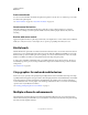
52 Chapter 3: Drawing Click on the following links to learn various drawing techniques and to gather more insights on drawing using Illustrator. Understand how to draw lines, shapes and various other geometrical forms. Drawing basics You draw and modify paths using a set of drawing tools and techniques common to Adobe Illustrator, Adobe® InDesign®, and Adobe® Photoshop®. Use these applications to draw paths, and freely copy and paste them between programs.
53 USING ILLUSTRATOR Drawing Paths can have two kinds of anchor points: corner points and smooth points. At a corner point, a path abruptly changes direction. At a smooth point, path segments are connected as a continuous curve. You can draw a path using any combination of corner and smooth points. If you draw the wrong kind of point, you can always change it. A B C Points on a path A. Four corner points B. Four smooth points C.
54 USING ILLUSTRATOR Drawing A smooth point always has two direction lines, which move together as a single, straight unit. When you move a direction line on a smooth point, the curved segments on both sides of the point are adjusted simultaneously, maintaining a continuous curve at that anchor point. In comparison, a corner point can have two, one, or no direction lines, depending on whether it joins two, one, or no curved segments, respectively.
55 USING ILLUSTRATOR Drawing 2 In the Control panel, click Show Handles For Multiple Selected Anchor Points Selected Anchor Points > or Hide Handles For Multiple . Note: You can also set a preference to always show or always hide handles when multiple anchor points are selected. Set direction point and direction line display preferences 1 Choose Edit > Preferences > Selection & Anchor Display (Windows) or Illustrator > Preferences > Selection & Anchor Display (Mac OS).
56 USING ILLUSTRATOR Drawing The Draw Normal mode is the default drawing mode. You can select drawing modes from the Tools panel, below the Color Selector tool. Drawing Modes panel To switch through drawing modes, click the Drawing Modes panel in the Tools panel and select the drawing mode. You can also use the Shift+D keyboard shortcut to cycle through the drawing modes. Note: The options, Paste, Paste in Place, and Paste on All Artboards honor the drawing modes.
57 USING ILLUSTRATOR Drawing • Click where you want the line to begin, and specify the length and angle of the line. If you want to fill the line with the current fill color, select Fill Line. Then click OK. More Help topics “Drawing tool gallery” on page 19 “Keys for drawing” on page 479 Draw rectangles and squares 1 Select the Rectangle tool or the Rounded Rectangle tool . 2 Do one of the following: • To draw a rectangle, drag diagonally until the rectangle is the desired size.
58 USING ILLUSTRATOR Drawing 2 Do one of the following: • Drag diagonally until the ellipse is the desired size. • Click where you want the top-left corner of the ellipse’s bounding box to be. Specify a width and height for the ellipse, and click OK. Note: To create a circle, hold down the Shift key while dragging, or if you are specifying dimensions, once you’ve entered a Width value you can click on the word Height to copy that value into the Height box. For a video on using shape tools, see www.adobe.
59 USING ILLUSTRATOR Drawing More Help topics “Drawing tool gallery” on page 19 “Keys for drawing” on page 479 Draw arcs 1 Select the Arc tool . 2 Do one of the following: • Position the pointer where you want the arc to begin, and drag to where you want the arc to end. • Click where you want the arc to begin. In the dialog box, click a square on the reference point locator to determine the point from which the arc is drawn. Then set any of the following options, and click OK.
60 USING ILLUSTRATOR Drawing More Help topics “Drawing tool gallery” on page 19 “Keys for drawing” on page 479 Draw grids Use the grid tools to quickly draw rectangular and polar grids. The Rectangular Grid tool creates rectangular grids of a specified size with a specified number of dividers. The Polar Grid tool creates concentric circles of a specified size and a specified number of dividers.
61 USING ILLUSTRATOR Drawing Create Compound Path From Ellipses Converts the concentric circles into separate compound paths and fill every other circle. Fill Grid Fills the grid with the current fill color (otherwise, the fill is set to none). Drawing pixel-aligned paths for web workflows Pixel-aligned is an object level property, which enables an object to have its vertical and horizontal paths aligned to the pixel grid. This property remains with the object when the object is modified.
62 USING ILLUSTRATOR Drawing A B Align New Objects to Pixel Grid option in the Transform panel menu If you enable this option, any new objects that you draw have the pixel-aligned property set by default. For new documents created using the web document profile, this option is enabled by default. The crisp appearance of pixel-aligned strokes is maintained in the raster output at a resolution of 72-ppi only.
63 USING ILLUSTRATOR Drawing Bringing non-aligned objects into documents with the Align New Objects to Pixel Grid option enabled, does not automatically pixel-align such objects. To make such objects pixel-aligned, select the object and then select the Align to Pixel Grid option from the Transform panel. You cannot pixel-align objects such as rasters, raster effects, and text objects because such objects do not have real paths.
64 USING ILLUSTRATOR Drawing Text anti-aliasing options in the Character panel You can set anti-aliasing options for each text frame. These text anti-aliasing attributes get saved as part of the document. These options are also supported for PDF, AIT, and EPS formats. Text anti-aliasing options can be exported to or imported from PSD. While exporting to BMP, PNG, Targa, JPEG, or TIFF formats the following options are available in the anti-aliasing drop-down list: None, Art Optimized and Type Optimized.
65 USING ILLUSTRATOR Drawing Draw closed paths with the Pencil tool 1 Select the Pencil tool. 2 Position the tool where you want the path to begin, and start dragging to draw a path. 3 After you’ve begun dragging, hold down Alt (Windows) or Option (Mac OS). The Pencil tool displays a small circle (and, in InDesign, a solid eraser) to indicate that you’re creating a closed path. 4 When the path is the size and shape you want, release the mouse button (but not the Alt or Option key).
66 USING ILLUSTRATOR Drawing Using the Pencil tool to edit a closed shape Note: Depending on where you begin to redraw the path and in which direction you drag, you may get unexpected results. For example, you may unintentionally change a closed path to an open path, change an open path to a closed path, or lose a portion of a shape.
67 USING ILLUSTRATOR Drawing Clicking Pen tool creates straight segments. 1 Select the Pen tool. 2 Position the Pen tool where you want the straight segment to begin, and click to define the first anchor point (do not drag). Note: The first segment you draw will not be visible until you click a second anchor point. (Select the Rubber Band option in Photoshop to preview path segments.) Also, if direction lines appear, you’ve accidentally dragged the Pen tool; choose Edit > Undo, and click again.
68 USING ILLUSTRATOR Drawing Hold down the Shift key to constrain the tool to multiples of 45°. A B C Drawing the first point in a curve A. Positioning Pen tool B. Starting to drag (mouse button pressed) C. Dragging to extend direction lines 4 Position the Pen tool where you want the curve segment to end, and do one of the following: • To create a C-shaped curve, drag in a direction opposite to the previous direction line. Then release the mouse button.
69 USING ILLUSTRATOR Drawing 6 Complete the path by doing one of the following: • To close the path, position the Pen tool over the first (hollow) anchor point. A small circle appears next to the Pen tool pointer when it is positioned correctly. Click or drag to close the path. Note: To close a path in InDesign, you can also select the object and choose Object > Paths > Close Path. • To leave the path open, Ctrl-click (Windows) or Command-click (Mac OS) anywhere away from all objects.
70 USING ILLUSTRATOR Drawing 3 Position the pen where you want the next anchor point; then click (and drag, if desired) the new anchor point to complete the curve. A B C Drawing a straight segment followed by a curved segment (part 2) A. Positioning Pen tool B. Dragging direction line C. New curve segment completed Draw curves followed by straight lines 1 Using the Pen tool, drag to create the first smooth point of the curved segment, and release the mouse button.
71 USING ILLUSTRATOR Drawing 3 Reposition the Pen tool where you want the second curved segment to end, and drag a new smooth point to complete the second curved segment. A B C Drawing two curves A. Dragging a new smooth point B. Pressing Alt/Option to split direction lines while dragging, and swinging direction line up C.
72 USING ILLUSTRATOR Drawing Copy a path ❖ Select a path or segment with the Selection tool or Direct Selection tool and do one of the following: • Use the standard menu functions to copy and paste paths within or between applications. • Press and hold Alt (Windows) or Option (Mac OS) and drag the path to the desired position, and then release the mouse button and Alt/Option key. Adjust path segments Editing path segments works similarly in Adobe applications.
73 USING ILLUSTRATOR Drawing Click to select the curve segment. Then drag to adjust. • To adjust the shape of the segment on either side of a selected anchor point, drag the anchor point or the direction point. Shift-drag to constrain movement to multiples of 45°. Drag the anchor point, or drag the direction point. Note: You can also apply a transformation, such as scaling or rotating, to a segment or anchor point.
74 USING ILLUSTRATOR Drawing • To connect a new path to an existing path, draw the new path near the existing path, and then move the Pen tool to the existing path’s (unselected) endpoint. Click that endpoint when you see the small merge symbol that appears next to the pointer. In InDesign, you can also use the Pathfinder panel to join paths. To close the path of an open path, use the Selection tool to select the path and click Close Path in the Pathfinder panel.
75 USING ILLUSTRATOR Drawing Note: In Illustrator and InDesign, you can change the distance of a nudge by changing the Keyboard Increment preference. When you change the default increment, holding down Shift nudges 10 times the specified distance. Stretch parts of a path without distorting its overall shape 1 Select the entire path. 2 Select the Reshape tool (located under the Scale tool ).
76 USING ILLUSTRATOR Drawing 2 Choose Select > Object > Stray Points. 3 Choose Edit > Cut or Edit > Clear commands, or press Delete or Backspace on the keyboard. Disable or temporarily override automatic Pen tool switching You can temporarily override or disable automatic switching to the Add Anchor Point tool or Delete Anchor Point tool. • To temporarily override switching, hold down Shift as you position the Pen tool over the selected path or an anchor point.
77 USING ILLUSTRATOR Drawing Simplify paths Simplifying a path removes extra anchor points without changing the shape of the path. Removing unnecessary anchor points simplifies your artwork, reducing the file size, and making it display and print faster. 1 Select the object. 2 Choose Object > Path > Simplify. 3 Set the Curve Precision to control how closely the simplified path follows the original path.
78 USING ILLUSTRATOR Drawing 2 To convert one or more smooth points to corner points, select the points and then click the Convert Selected Anchor Points To Corner button in the Control panel. Convert an anchor point precisely using the Convert Anchor Point tool 1 Select the entire path you want to modify so that you can see its anchor points. 2 Select the Convert Anchor Point tool .
79 USING ILLUSTRATOR Drawing Erase artwork You can erase portions of your artwork using the Path Eraser tool, the Eraser tool, or the eraser on a Wacom stylus lets you erase parts of a path by drawing along the path. This tool is useful when you pen. The Path Eraser tool want to limit what you erase to a path segment, such as one edge of a triangle. The Eraser tool and the eraser on a Wacom stylus pen let you erase any area of your artwork, regardless of structure.
80 USING ILLUSTRATOR Drawing Erase objects using a Wacom stylus pen eraser When you flip a stylus pen, the Eraser Tool automatically becomes active. When you flip the stylus pen back over, the last active tool becomes active again. ❖ Turn over the stylus pen and drag across the area you want to erase. Press harder to increase the width of the erased path. (You may need to select the Pressure option in the Eraser Tool Options dialog box first.
81 USING ILLUSTRATOR Drawing • Any paths resulting from a split inherit the path settings of the original path, such as stroke weight and fill color. Stroke alignment is automatically reset to center. 1 (Optional) Select the path to see its current anchor points. 2 Do one of the following: • Select the Scissors tool and click the path where you want to split it. When you split the path in the middle of a segment, the two new endpoints appear on top of the other, and one endpoint is selected.
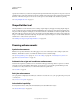
82 USING ILLUSTRATOR Drawing • Click the Perspective Grid tool from the Tools panel. A B C D E F I G J K L H M N O P Q Perspective Grid A. Plane switching widget B. Left Vanishing Point C. Vertical Grid Extent D. Perspective Grid Ruler E. Right Vanishing Point F. Horizon Line G. Horizon Height H. Ground Level I. Horizon Level J. Extent of Grid K. Grid Cell Size L. Ground Level M. Extent of Grid N. Right Grid Plane Control O. Horizontal Grid Plane Control P. Left Grid Plane Control Q.
83 USING ILLUSTRATOR Drawing B C A D A. Left Grid Plane B. No Active Grid Plane C. Right Grid Plane D. Horizontal Grid Plane Plane Switching Widget For a video on defining the perspective grid, see www.adobe.com/go/lrvid5205_ai_en. You can set options to position the widget on any of the four screen corners and choose to display it when the Perspective Grid is visible. To set these options, double-click the Perspective Grid icon in the Tools panel.
84 USING ILLUSTRATOR Drawing A B C Perspective Grid Presets A. 1-point perspective B. 2-point perspective (default) C. 3-point perspective To select one of the default perspective grid preset, click View> Perspective Grid and then select from the required preset. Define grid presets To define grid settings, click View > Perspective Grid > Define Grid.
85 USING ILLUSTRATOR Drawing Viewing Angle Imagine a cube in such an orientation that no face is parallel to the picture plane (in this case the computer screen). Viewing Angle is the angle which the right face of this imaginary cube makes with the picture plane. Therefore, the viewing angle determines the positions of the left and right vanishing points from the observer. A viewing angle of 45° implies that the two vanishing points are equidistant from the line of vision of the observer.
86 USING ILLUSTRATOR Drawing You cannot delete the default presets. To delete a user-defined preset, click Delete in the Perspective Grid Presets dialog box. Illustrator also allows you to import and export user-defined presets. To export a particular preset, click Export in the Perspective Grid Presets dialog box. To import a preset, click Import. Move the perspective grid Illustrator can create only one grid in an Illustrator document.
87 USING ILLUSTRATOR Drawing Moving the right vanishing point in a two-point perspective grid Note: If you lock the station point using the View > Perspective Grid > Lock Station Point option, then both the vanishing points move together. Both vanishing points move when station point is locked. You can also adjust the left, right, and horizontal grid planes using the respective grid plane control widgets.
88 USING ILLUSTRATOR Drawing Adjusting the left and right grid planes in a two-point perspective If you shift the origin, the x and y coordinates of the horizontal plane and the x coordinate of vertical planes are affected. When you select an object in perspective while the grid is visible, the x and y coordinates displayed in the Transform and Info panels change with shift in origin.
89 USING ILLUSTRATOR Drawing Adjust horizon height to fine-tune the observer's eye-level. When you move the pointer over the horizon line, the pointer changes to a vertical two-way arrow . Adjusting the horizon height in a two-point perspective grid You can change the grid extent to define the extent of the grid on the planes. When you move the pointer over the grid extent widgets, the pointer changes to . Note: Gridlines are set to display onscreen when there is a 1-pixel gap in them.
90 USING ILLUSTRATOR Drawing To increase or decrease the grid cell size, use the grid cell size widget. When you mouse over the grid cell size widget, the pointer changes to . Note: When you increase the grid cell size, the number of grid cells reduce. Increasing the grid cell size by dragging the grid cell size widget. Drawing new objects in perspective To draw objects in perspective, use the line group tools or rectangle group tools while the grid is visible.
91 USING ILLUSTRATOR Drawing To add an object to the left, right, or horizontal grid: 1 Select the active plane on which you want to place the object. You can select the active plane using 1, 2, or 3 keyboard shortcut command or by clicking on one of the faces of the cube in the Perspective Grid Widget. 2 Click Object > Perspective > Attach to Active Plane. Note: Using the Attach to Active Plane command does not affect the appearance of the object. For a video on mapping artwork to perspective, see www.
92 USING ILLUSTRATOR Drawing Moving a rectangle in perpendicular to its initial position Note: The arrow keys do not work when you move objects in perpendicular. Use the keyboard shortcut, Alt+drag (Windows) or Option+drag (Mac OS) to copy the object. To constrain the movement in perspective, press Shift+drag. To specify a precise location where you need to move the object during perpendicular movement, see “Precise perpendicular movement” on page 92.
93 USING ILLUSTRATOR Drawing For precise perpendicular movement, for all objects: 1 In the Location box, specify the location where the objects need to be moved. By default, the current location of objects is displayed in the dialog box. 2 Select from the following movement options for objects: Do Not Move If this option is selected, the object does not move when the grid is repositioned. Move All Objects If you select this option, then all the objects on the plane move with the grid movement.
94 USING ILLUSTRATOR Drawing 2 Press Alt and drag (Windows) or Option and drag (Mac OS) the grid plane control depending on the grid plane where the object is placed. Automatic plane positioning The automatic plane positioning feature allows you to create objects by inferring the height or depth of the object. For example, to draw a cube, the height of the top face of the cube must be known.
95 USING ILLUSTRATOR Drawing After creating the top face of the cube using the rectangle tool, the grid resumes its original state Before drawing or placing objects, the object height can be inferred from: • Other objects by going to one of the anchor points (getting the anchor label) and pressing Shift, which temporarily hides other planes. • Grid lines by going to the intersection point and pressing the Shift key. Changing plane in this state brings that plane to the selected offset.
96 USING ILLUSTRATOR Drawing Move plane to match object When you want to draw or bring objects in perspective at the same depth or height as an existing object, select the existing object in perspective and click Object > Perspective > Move Plane to Match Object to bring the corresponding grid to the desired height or depth. You can now draw or bring new objects in perspective. Scale objects in perspective You can scale objects in perspective using the Perspective Selection tool.
97 USING ILLUSTRATOR Drawing You can edit or modify text in the same way as is done in the normal mode. For more information, see “Creating text” on page 308. Perspective Grid settings You can configure the Perspective Grid settings using View > Perspective Grid. The options available include: Show Rulers This option shows the ruler division only along the true height line. The gridline every determines the ruler division.
98 USING ILLUSTRATOR Drawing • To set tracing options before you trace the image, click the Tracing Presets and Options button in the Control panel, and choose Tracing Options. Alternatively, choose Object > Live Trace > Tracing Options. Set tracing options, and then click Trace. 3 (Optional) Adjust the results of the tracing. 4 (Optional) Convert the tracing to paths or to a Live Paint object. Tracing options Preset Specifies a tracing preset. Mode Specifies a color mode for the tracing result.
99 USING ILLUSTRATOR Drawing Select Preview in the Tracing Options dialog box to preview the result of the current settings.To set the default tracing options, deselect all objects before you open the Tracing Options dialog box. When you’re finished setting options, click Set Default. For a video on using Live Trace, see www.adobe.com/go/vid0043. For a tutorial on tweaking Live Trace options for the best possible results, see www.adobe.com/go/learn_ai_tutorials_livetrace_en.
100 USING ILLUSTRATOR Drawing Use a tracing preset Tracing presets provide pre-specified tracing options for specific types of artwork. For example, if you’re tracing an image that you plan to use as a technical drawing, choose the Technical Drawing preset. All the tracing options change for optimal tracing of a technical drawing: color is set to black and white, blur is set to 0 px, stroke width is limited to 3 px, and so on. Specify a preset • Choose Object > Live Trace > Tracing Options.
101 USING ILLUSTRATOR Drawing To create a tracing and convert the tracing object in one step, choose Object > Live Trace > Make And Expand or Object > Live Trace > Make And Convert To Live Paint. For a video on tracing, see www.adobe.com/go/vid0043. More Help topics “About paths” on page 52 “About Live Paint” on page 162 Release a tracing object If you want to discard a tracing but keep the original placed image, you can release the tracing object. 1 Select the tracing object.
102 USING ILLUSTRATOR Drawing Symbols also provide excellent support for SWF and SVG export. When you export to Flash, you can set the symbol type to MovieClip. Once in Flash, you can choose another type if necessary. You can also specify 9-slice scaling in Illustrator so that the symbols scale appropriately when used for user interface components. Note: For information on using symbols in Flash, see Flash Help. For a video on using symbols effectively, see www.adobe.com/go/lrvid5204_ai_en.
103 USING ILLUSTRATOR Drawing Rename a symbol 1 To rename the symbol, select the symbol in the Symbols panel, choose Symbol Options from the panel menu, and then type a new name in the Symbol Options dialog box. 2 To rename a symbol instance, select a symbol instance in the artwork, and then type a new name in the Instance Name text box in the Control panel. Symbol registration point The symbol registration point in Illustrator is similar to Adobe Flash Professional.
104 USING ILLUSTRATOR Drawing 4 Select the symbol type as Movie Clip or Graphic. If you plan to export the symbols to Flash, do the following: • Select Movie Clip for type. Movie Clip is the default symbol type in Flash and in Illustrator. • Specify a location on the Registration grid where you want to set the symbol’s anchor point. The location of the anchor point affects the position of the symbol within the screen coordinates.
105 USING ILLUSTRATOR Drawing Enable 9-slice scaling 1 Select the symbol on the artboard or in the Symbols panel and choose Symbol Options from the panel menu. 2 In the Symbol Options dialog box, select Movie Clip or Graphic for Type, and then select Enable Guides For 9-Slice Scaling. Note: You can also enable this option in the Symbol Options dialog box when creating a new symbol.
106 USING ILLUSTRATOR Drawing 4 (Optional) do one of the following: • To replace the parent symbol with this edited version, Alt-drag (Windows) or Option-drag (Mac OS) the modified symbol on top of the old symbol in the Symbols panel. The symbol is replaced in the Symbols panel and is updated in the current file. • To create a new symbol with this edited version, drag the modified symbol to the Symbols panel or click New Symbol in the Symbols panel.
107 USING ILLUSTRATOR Drawing Edit or redefine a symbol You can edit a symbol by changing the symbol’s artwork or you can redefine the symbol by replacing it with new artwork. Editing and redefining a symbol changes the appearance of the symbol in the Symbols panel, as well as all instances of the symbol on the artboard. Edit a symbol 1 Do one of the following to open the symbol in isolation mode: • Select an instance of the symbol and click Edit Symbol in the Control panel.
108 USING ILLUSTRATOR Drawing Move symbols from a library into the Symbols panel A symbol is automatically added to the Symbols panel whenever you use it in a document. ❖ Click a symbol in a library. Create symbol libraries 1 To add all the symbols from a library, Shift select all the symbols and choose Add to Symbols from the Symbol Library option menu. Add the symbols you want in the library to the Symbols panel, and delete any symbols you don’t want.
109 USING ILLUSTRATOR Drawing As you work with symbol sets, keep in mind that the symbolism tools affect only the symbol or symbols selected in the Symbols panel. For example, if you create a mixed symbol instance set that represents a meadow with grass and flowers, you can change the orientation of just the grass by selecting the grass symbol in the Symbols panel and then using the Symbol Spinner tool.
110 USING ILLUSTRATOR Drawing 2 Do one of the following: • To move symbol instances, drag in the direction you want the symbol instances to move. • To bring symbol instances forward, Shift-click the symbol instance. • To send symbol instances backward, hold down Alt (Windows) or Option (Mac OS) and Shift-click the symbol instance. Gather or scatter symbol instances 1 Select the Symbol Scruncher tool .
111 USING ILLUSTRATOR Drawing Adjust transparency of symbol instances 1 Select the Symbol Screener tool . 2 Do one of the following: • Click or drag where you want to increase the symbol’s transparency. • Hold down Alt (Windows) or Option (Mac OS), and click or drag where you want to decrease the symbol’s transparency. Apply a graphic style to symbol instances The Symbol Styler tool lets you apply or remove a graphic style from a symbol instance.
112 USING ILLUSTRATOR Drawing General options, such as diameter, intensity, and density, appear at the top of the dialog box. Tool-specific options appear at the bottom of the dialog box. To switch to options for a different tool, click a tool icon in the dialog box. General options The General options appear at the top of the Symbolism Tools Options dialog box regardless of which symbolism tool is selected. • Diameter Specifies the tool’s brush size.
113 USING ILLUSTRATOR Drawing A C B D E Components of a flare A. Center handle B. End handle C. Rays (shown black for clarity) D. Halo E. Rings To learn more about creating and editing flares, see this topic in web Help. Important: Complete, updated Help is on the web. The application did not detect an Internet connection. For a complete version of this topic, click the link below or search complete Help at community.adobe.com/help.
114 USING ILLUSTRATOR Drawing 2 Press the mouse button down to place the center handle of the flare, then drag to set the size of the center, the size of the halo, and to rotate the angle of the rays. Before releasing the mouse, press Shift to constrain the rays to a set angle. Press Up Arrow or Down Arrow to add or subtract rays. Press Ctrl (Windows) or Command (Mac OS) to hold the center of the flare constant. 3 Release the mouse when the center, halo, and rays are as desired.
115 Chapter 4: Color Click on the following links to learn how to apply colors using Illusrator. Navigate to other links to understand the intricacies of applying color. About color Applying colors to artwork is a common Adobe Illustrator task, and one that requires some knowledge of color models and color modes. When applying color to artwork, keep in mind the final medium in which the artwork will be published, so that you can use the correct color model and color definitions.
116 USING ILLUSTRATOR Color G R B Additive colors (RGB) R. Red G. Green B. Blue You can work with color values using the RGB color mode, which is based on the RGB color model. In RGB mode, each of the RGB components can use a value ranging from 0 (black) to 255 (white). For example, a bright red color might have an R value of 246, a G value of 20, and a B value of 50. When the values of all three components are equal, the result is a shade of gray.
117 USING ILLUSTRATOR Color You can work with color values using the CMYK color mode, which is based on the CMYK color model. In CMYK mode, each of the CMYK process inks can use a value ranging from 0 to 100%. The lightest colors are assigned small percentages of process ink colors; darker colors have higher percentage values. For example, a bright red might contain 2% cyan, 93% magenta, 90% yellow, and 0% black.
118 USING ILLUSTRATOR Color In Illustrator, you can use the Lab model to create, display, and output spot color swatches. However, you cannot create documents in Lab mode. More Help topics “Display and output spot colors using Lab values” on page 148 Grayscale Grayscale uses tints of black to represent an object. Every grayscale object has a brightness value ranging from 0% (white) to 100% (black). Images produced using black-and-white or grayscale scanners are typically displayed in grayscale.
119 USING ILLUSTRATOR Color About spot and process colors You can designate colors as either spot or process color types, which correspond to the two main ink types used in commercial printing. In the Swatches panel, you can identify the color type of a color using icons that appear next to the name of the color. When applying color to paths and frames, keep in mind the final medium in which the artwork will be published, so that you apply color using the most appropriate color mode.
120 USING ILLUSTRATOR Color • Don’t specify a process color based on how it looks on your monitor, unless you are sure you have set up a colormanagement system properly, and you understand its limitations for previewing color. • Avoid using process colors in documents intended for online viewing only, because CMYK has a smaller color gamut than that of a typical monitor. • Illustrator and InDesign let you specify a process color as either global or non-global.
121 USING ILLUSTRATOR Color You can use any of the following features for selecting color: Swatches panel and swatch library panels Provide individual colors and color groups. You can choose from preexisting swatches and libraries or create your own. You can also import libraries. Color Picker Provides a color spectrum from which you can visually select colors, color value text boxes for manually defining colors, and color swatches. Eyedropper tool Samples colors from your artwork when you click.
122 USING ILLUSTRATOR Color A E F B CD G H I Color Picker A. Color field B. HSB color values C. New color rectangle D. Original color rectangle E. Color slider F. Color spectrum G. RGB color values H. Hexadecimal color value I. CMYK color values More Help topics “About colors in digital graphics” on page 115 Display the Color Picker ❖ Double-click the fill or stroke color selection box in the Tools panel or Color panel.
123 USING ILLUSTRATOR Color Color panel overview You use the Color panel (Window > Color) to apply color to an object’s fill and stroke, and also to edit and mix colors. The Color panel can display color values using different color models. By default, only the most commonly used options are visible in the Color panel. AB D C E F G Color panel A. Fill color B. Stroke color C. panel menu D. None box E. Color spectrum bar F. Color slider G.
124 USING ILLUSTRATOR Color Using and creating swatches About swatches Swatches are named colors, tints, gradients, and patterns. The swatches associated with a document appear in the Swatches panel. Swatches can appear individually or in groups. You can open libraries of swatches from other Illustrator documents and various color systems. Swatch libraries appear in separate panels and are not saved with the document.
125 USING ILLUSTRATOR Color A B C D E F G H I J K Swatches panel in Small List view A. Spot color B. Global color C. Fill or stroke of None D. Registration swatch (prints on all plates) E. CMYK symbol (when document is open in CMYK mode) F. RGB symbol (when document is open in RGB mode) G. Swatch Library Menu button H. Show Swatch Kinds Menu button I. Swatch Options button J. New Color Group button K.
126 USING ILLUSTRATOR Color Move swatches into a color group 1 Drag individual color swatches to an existing color group folder. 2 Select the colors you want in a new color group and click the New Color Group button . Change the order of swatches You can reorder individual swatches as well as swatches inside a color group. ❖ Do one of the following: • Select Sort By Name or Sort By Kind from the Swatches panel menu. These commands only work on individual swatches, not swatches in a color group.
127 USING ILLUSTRATOR Color Edit a swatch library 1 Choose File > Open, locate and open the library file. By default, swatch library files are stored in the Illustrator/Presets/Swatches folder. 2 Edit the colors in the Swatches panel and save your changes. Move swatches from a swatch library to the Swatches panel Do any of the following: • Drag one or more swatches from the swatch library panel to the Swatches panel.
128 USING ILLUSTRATOR Color Note: You can create and share color group swatches by using the Kuler panel or the Kuler website. (See “Kuler panel” on page 145.) 1 In the Swatches panel, create the process and spot-color swatches you want to share, and remove any swatches you don’t want to share.
129 USING ILLUSTRATOR Color 2 Do one of the following: • Drag the color from the Tools panel or Color panel to the Swatches panel. • In the Swatches panel, click the New Swatch button or select New Swatch from the panel menu. In the dialog box that appears, select Global if you want the swatch to be a global color. Set additional swatch options, and click OK. (See “Swatch options” on page 130.
130 USING ILLUSTRATOR Color Group swatches When you want to keep specific colors together in the Swatches panel, create a color group. For example, you can create a color group for colors you select in the Color Guide panel. When you save a color group in the Edit Colors dialog box, it is automatically saved as a color group in the Swatches panel. You can also manually group any set of solid color swatches. 1 Select one or more swatches in the Swatches panel.
131 USING ILLUSTRATOR Color You can use the Color Guide panel or the Edit Colors/Recolor Artwork dialog box to create harmonious color groups. Using either feature, you can choose a harmony rule to instantly generate a color scheme based on any color you want. For example, choose the Monochromatic harmony rule to create a color group containing all the same hue, but with different saturation levels.
132 USING ILLUSTRATOR Color Show Vivid/Muted Decreases the saturation toward gray in variations on the left and increases saturation toward gray in variations on the right Note: If you’re using spot colors, use only the Tints/Shades variation and choose colors from the tint (right) side of the variation grid. All other variations cause spot colors to be converted to process.
133 USING ILLUSTRATOR Color A B C Create or edit color groups, and assign colors using the Edit Colors/Recolor Artwork dialog box. A. Create and edit a color group in the Edit tab B. Assign colors in the Assign tab C. Select a color group from the Color Groups list The Recolor Art option at the bottom of the dialog box lets you preview colors on selected artwork, and specifies whether artwork is recolored when you close the dialog box.
134 USING ILLUSTRATOR Color Open the Edit Colors/Recolor Artwork dialog box ❖ Open the Edit Colors/Recolor Artwork dialog box from any of the following locations: Edit > Edit Colors > Recolor Artwork or Recolor With Presets command Use these commands when you want to edit colors in selected artwork. in Control panel Use this button when you want to edit the colors of the selected artwork using the Recolor Artwork dialog box. This button is available when the selected artwork contains two or more colors.
135 USING ILLUSTRATOR Color • Double-click the Fill Color in the Tools panel and pick a color in the Color Picker. • Using the eyedropper, click artwork containing the color you want. • Select artwork containing the color you want, and then click the Set Base Color To The Current Color icon . • Click a color variation in the Color Guide panel, and then click the Set Base Color To The Current Color icon . 2 Choose a rule from the Harmony Rules menu.
136 USING ILLUSTRATOR Color Note: Recolor Art will recolor selected artwork when you click OK to close the dialog box. If you don’t want to recolor the selected art, make sure to deselect this option before clicking OK. 6 Type a name in the Name box to the right of the Harmony Rules menu, and click New Color Group . Note: if the New Color Group icon is not visible, click the Show Color Group Storage icon .
137 USING ILLUSTRATOR Color For a video on creating, editing, and experimenting with color groups, see www.adobe.com/go/lrvid4019_ai. To see an example of changing a vibrant color illustration to a grayscale illustration, see www.adobe.com/go/learn_ai_tutorials_depth_en. A B C D E A. Base color as it appears in Harmony Rules menu B. Base color as it appears in color wheel C. Color display options D. Color of selected color marker or color bar E. Show saturation and hue on Wheel F.
138 USING ILLUSTRATOR Color 5 Drag a marker on the wheel to change its color. If the harmony is linked, all the colors move according to the rule as you drag. If the harmony is unlinked, only the marker that you drag moves. While editing, you can do any of the following: a To change hue, move the marker around the wheel. To change saturation or brightness, move it inward and outward on the wheel. b To add a color, right-click in the color wheel where you want to add the color and choose Add New Color.
139 USING ILLUSTRATOR Color B A D C E F A. Color wheel view of linked colors B. Color wheel view of unlinked colors C. Color bars view of linked colors D. Color bars view of unlinked colors E. Colors linked, click to unlink F. Colors unlinked, click to relink 1 In the Edit Colors/Recolor Artwork dialog box, select the color group you want to edit and click Edit. 2 Click the Unlink Harmony Colors icon .
140 USING ILLUSTRATOR Color Edit colors in a color group using the Color Picker You can use the Color Picker to change colors in a color group. 1 In the Edit Colors/Recolor Artwork dialog box, do one of the following: • Double-click a wheel marker or right-click a wheel marker and choose Color Picker. • Double-click a color bar. • Click the color swatch to the left of the color sliders.
141 USING ILLUSTRATOR Color Delete a color group ❖ Select a color group in the Color Groups list and click Delete . Or right-click and choose Remove Color Group. Assign colors to your artwork The Assign tab of the Edit Colors/Recolor Artwork dialog box lets you assign colors from a color group to your artwork. You can assign colors in the following ways: • Assign new colors to your artwork using a color group from the Color Groups list.
142 USING ILLUSTRATOR Color A B C D E F A. Active color group B. Get Colors From Selected Art C. Colors from selected artwork D. New colors from active color group E. Options for working with entire rows F. Recolor Artwork For a video on assigning colors, see www.adobe.com/go/vid0061. Assign new colors to selected artwork 1 Select the artwork you want to recolor. 2 Choose Edit > Edit Colors > Recolor Artwork.
143 USING ILLUSTRATOR Color • To assign a new color to a different row of current colors, drag the new color up or down in the New column. (To add a new color to or remove a color from the New column, right-click in the list and choose Add New Color or Remove Color.) • To change a color in the New column, right-click it and choose Color Picker to set a new color. • To exclude a row of current colors from being reassigned, click the arrow between the columns. To include it again, click the dash.
144 USING ILLUSTRATOR Color Reduce colors in your artwork Reducing colors for output, converting colors to grayscale, or limiting colors to a color library is often necessary when you create artwork intended for multiple types of output media. You can easily reduce the number of colors in your artwork using the Recolor Artwork dialog box. You can choose whether to use a preset for reducing colors, for example, you can choose Grayscale Art to quickly convert your selected artwork to grayscale.
145 USING ILLUSTRATOR Color 5 Click the Color Reduction Options button , specify any of the following options, and click OK: Preset Specifies a preset color job, including the number of colors used and optimal settings for that job. If you select a preset and then change any of the other options, the preset changes to Custom. Colors Specifies the number of new colors that the current colors are reduced to. Limit To Library Specifies a swatch library from which all new colors are derived.
146 USING ILLUSTRATOR Color View and use themes An Internet connection is required to browse themes online. Search and view themes 1 Select Window > Extensions > Kuler. 2 In the Search box, enter the name of a theme, a tag, or a creator. Note: Use only alphanumerical characters (Aa-Zz, 0-9) in searches. 3 Filter the search results by selecting an option from the pop-up menus above the results.
147 USING ILLUSTRATOR Color Shift a color to a web-safe color Web-safe colors are the 216 colors used by all browsers, regardless of the platform. If you select a color that is not webappears in the Color panel, Color Picker, or Edit Colors/Recolor Artwork dialog box. safe, an alert cube ❖ Click the cube to shift to the closest web-safe color (which is displayed in a small box by the cube).
148 USING ILLUSTRATOR Color 3 To save the tint as a swatch, drag the color to the Swatches panel, or click the New Swatch button in the Swatches panel. The tint is saved with the same name as the base color, but with the tint percentage added to the name. For example, if you saved a color named “Sky Blue” at 50 percent, the swatch name would be “Sky Blue 50%.
149 USING ILLUSTRATOR Color Lab values, when used in conjunction with the correct device profiles, give you the most accurate output across all devices. If color management is critical to your project, Adobe recommends that you display, export, and print spot colors using their Lab values. Note: To improve on-screen accuracy, Illustrator uses the Lab values automatically if Overprint Preview is on.
150 USING ILLUSTRATOR Color 3 Enter a value from –100% to 100% to specify the percentage by which to decrease or increase the color or the spot- color tint. More Help topics “HSB” on page 117 Mix overlapping colors You can use blending modes, the Hard Mix effect, or the Soft Mix effect to mix overlapping colors.
151 Chapter 5: Painting About painting To help you add visual interest to your artwork, Adobe Illustrator provides calligraphic, scatter, art, pattern, and bristle brushes. In addition, you can use the Live Paint feature and Shape Builder tools, to paint different path segments and fill enclosed paths with different colors, patterns, or gradients. Using the Shape Builder tool, you can create new complex new shapes by merging simple shapes.
152 USING ILLUSTRATOR Painting Painting an object the traditional way leaves some areas that cannot be filled (left). Painting a Live Paint group with gap detection (center) lets you avoid gaps and overprinting (right). For a video on using Live Paint, see www.adobe.com/go/vid0042. For a video on painting techniques with the Paintbrush tool, see www.adobe.com/go/vid0038. More Help topics “About Live Paint” on page 162 About fills and strokes A fill is a color, pattern, or gradient inside an object.
153 USING ILLUSTRATOR Painting Default Fill And Stroke button Color button Click to apply the last-selected solid color to an object with a gradient fill or no stroke or fill. Click to change the currently selected fill to the last-selected gradient. Gradient button None button Click to return to the default color settings (white fill and black stroke). Click to remove the selected object’s fill or stroke.
154 USING ILLUSTRATOR Painting Stroke panel You can apply stroke options to an entire object, or you can use Live Paint groups and apply different strokes to different edges within the object. Layers Magazine instructor Dave Cross shows you how to apply fill and stroke in Illustrator and some handy shortcuts to work with fill and stroke in this video.
155 USING ILLUSTRATOR Painting Create dotted or dashed lines You can create a dotted or dashed line by editing an object’s stroke attributes. 1 Select the object. 2 In the Stroke panel, select Dashed Line. If the Dashed Line option isn’t showing, choose Show Options from the Stroke panel menu. 3 Click the icon: Align Dashes to Corners and Path Ends, Adjusting Length to Fit . This option allows you to make the dashes at the corners and ends of the paths consistent and predictable.
156 USING ILLUSTRATOR Painting If the options aren’t showing, choose Show Options from the panel menu. Butt Cap Creates stroked lines with squared ends. Round Cap Creates stroked lines with semicircular ends. Creates stroked lines with squared ends that extend half the line width beyond the end of the line. This option makes the weight of the line extend equally in all directions around the line. Projecting Cap Miter Join Creates stroked lines with pointed corners.
157 USING ILLUSTRATOR Painting Place the updated Arrowheads.ai file at: \Plug-ins\ and avoid replacing the existing Arrowheads.ai file. Draw and merge paths with the Blob Brush tool Use the Blob Brush tool to paint filled shapes that you can intersect and merge with other shapes of the same color. The Blob Brush tool uses the same default brush options as calligraphic brushes. (See “Calligraphic brush options” on page 175.
158 USING ILLUSTRATOR Painting 4 Draw paths that intersect with the artwork. If the paths don’t merge, check to make sure that the Blob Brush tool’s attributes exactly match the existing path attributes, and that neither uses a stroke. Blob Brush tool options Double-click the Blob Brush tool in the Tools panel and set any of the following options: Keep Selected Specifies that when you draw a merged path, all paths are selected and remain selected as you continue to draw.
159 USING ILLUSTRATOR Painting A B C Fill and Stroke boxes A. Fill box B. Stroke box C. None button Select objects with the same fill and stroke You can select objects that have the same attributes, including fill color, stroke color, and stroke weight. Note: The Select > Same > Fill Color, Stroke Color, and Stroke Weight commands work within a Live Paint group when you select a face or edge with the Live Paint Selection tool; other Select > Same commands do not work.
160 USING ILLUSTRATOR Painting Create strokes with variable widths About the Width tool The Width tool is available from the Tools panel. It allows you to create a variable width stroke and save the variable width as a profile that can be applied to other strokes. When you mouse over a stroke with the Width tool, a hollow diamond appears on the path with handles. You can adjust the stroke width, move the width point, duplicate the width point, and delete the width point.
161 USING ILLUSTRATOR Painting Discontinuous width point created by dragging one width point on to the other width point. For discontinuous points, the Width Point Edit dialog box shows both sets of side widths. Width Point Edit dialog box for discontinuous points The Single Width Only check boxes allow using either incoming or outgoing width leaving a single continuous width point.
162 USING ILLUSTRATOR Painting Saving width profiles After defining the stroke width, you can save the variable width profile from the Stroke panel or the Control panel. A B C D A. Uniform Width Profile option B. Save Width Profile icon C. Delete Width Profile icon D. Reset Width Profile icon Width profiles can be applied to selected paths by choosing them from the Width Profile drop-down list in the Control panel or Stroke panel.
163 USING ILLUSTRATOR Painting A B C Adjusting Live Paint paths A. Original B. Live Paint group C. Paths adjusted, Live Painting reflows The paintable parts of Live Paint groups are called edges and faces. An edge is the portion of a path between where it intersects with other paths. A face is the area enclosed by one or more edges. You can stroke edges and fill faces. Take, for example, a circle with a line drawn across it.
164 USING ILLUSTRATOR Painting • Make Opacity Mask (in the Transparency panel menu) • Brushes (You can apply brushes to an entire Live Paint group if you add a new stroke to the group using the Appearance panel.
165 USING ILLUSTRATOR Painting Create a Live Paint group 1 Select one or more paths, compound paths, or both. 2 Do one of the following: • Choose Object > Live Paint > Make. • Select the Live Paint Bucket tool and click the selected object. Note: Certain properties may be lost in the conversion to a Live Paint group, such as transparency and effects, while other objects cannot be converted (such as type, bitmap images, and brushes).
166 USING ILLUSTRATOR Painting Select items in Live Paint groups Use the Live Paint Selection tool to select individual faces and edges in a Live Paint group. Use the Selection tool to select the entire Live Paint group, and the Direct Selection tool to select paths inside a Live Paint group. When you’re working in a complex document, you can isolate a Live Paint group so that it is easy to select the exact face or edge you want.
167 USING ILLUSTRATOR Painting Live Paint group before (left) and after adjusting paths (right) When you delete edges, the fill floods across any newly expanded face. For example, if you delete a path that divides a circle in half, the circle is filled with one of the fills previously in the circle. You can sometimes help guide the results. For instance, before deleting a path that divides a circle, first move it so that the fill you want to keep is larger than the fill you want to remove.
168 USING ILLUSTRATOR Painting Note: Paths inside a Live Paint group may not exactly align with similar or identical paths outside the Live Paint group. Resize an individual object or path ❖ Do one of the following: • Using the Direct Selection tool, click the path or object to select it. Then choose the Selection tool and click the path or object again to edit it. • Using the Selection tool, double-click the Live Paint Group to put it into isolation mode. Then click a path or object to edit it.
169 USING ILLUSTRATOR Painting More Help topics “Tools panel overview” on page 16 “Fill and Stroke controls” on page 152 “Apply a fill color to an object” on page 153 “Stroke an object” on page 153 Live Paint Bucket options The Live Paint Bucket options let you specify how the Live Paint Bucket tool works, choosing whether to paint just fills, just strokes, or both, as well as how to highlight faces and edges as you move the tool over them.
170 USING ILLUSTRATOR Painting Gap Preview Color Sets the color for previewing gaps in Live Paint groups. You can choose a color from the menu, or click the color well next to the Gap Preview Color menu to specify a custom color. Close Gaps With Paths When selected, inserts unpainted paths into your Live Paint group to close gaps (rather than simply preventing paint from flowing though the gaps).
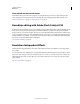
171 USING ILLUSTRATOR Painting A B C D E A. Calligraphic Brush B. Scatter Brush C. Art Brush D. Pattern Brush E. Bristle Brush Scatter brushes and Pattern brushes can often achieve the same effect. However, one way in which they differ is that Pattern brushes follow the path exactly, while Scatter brushes do not. Arrows in a Pattern brush bend to follow the path (left), but arrows remain straight in a Scatter brush (right). For a video on using brushes, see www.adobe.com/go/vid0044.
172 USING ILLUSTRATOR Painting Change the order of brushes in the Brushes panel ❖ Drag a brush to a new location. You can move brushes only within their type. For example, you cannot move a Calligraphic brush to the Scatter brush area. Duplicate a brush in the Brushes panel ❖ Drag the brush onto the New Brush button or choose Duplicate Brush from the Brushes panel menu. Delete the brushes from the Brushes panel ❖ Select the brushes and click the Delete Brush button .
173 USING ILLUSTRATOR Painting • Drag a brush onto the path. If the path already has brush strokes applied to it, then the new brush replaces the old brush. If you want to apply a different brush to the path and want to use the brush stroke settings used with the original brush, hold down Alt (Win) or Option (Mac OS) when clicking the new brush you want to apply. Draw paths and apply brush strokes simultaneously 1 Select a brush in a brush library or the Brushes panel. 2 Select the Paintbrush tool .
174 USING ILLUSTRATOR Painting Convert brush strokes to outlines You can convert brush strokes into outlined paths to edit the individual components of a brushed path. 1 Select a brushed path. 2 Choose Object > Expand Appearance. Illustrator places the components of the expanded path in a group. Within the group are a path and a subgroup containing the brush stoke outlines.
175 USING ILLUSTRATOR Painting • To modify a brushed path without updating the corresponding brush, select the path and click the Options Of Selected Object button (flyout menu). in the Brushes panel or select options of selected object from the Brushes panel menu Brush options You can specify different options for the different types of brushes. To change the options for a brush, double-click the brush in the Brushes panel. Scatter, Art, and Pattern brushes all have identical options for colorization.
176 USING ILLUSTRATOR Painting Colorization options for scatter, art, and pattern brushes The colors that a scatter, art, or pattern brush paints depend on the current stroke color and the colorization method of the brush. To set the colorization method, select one of the following options in the Brush Options dialog box: None Displays colors as they appear in the brush in the Brushes panel. Choose None to keep a brush the same colors as in the Brushes panel.
177 USING ILLUSTRATOR Painting • Tilt Creates a brush that varies in angle, roundness, or diameter based on the tilt of a drawing stylus. It is available only if you have a graphics tablet that can detect how close to vertical the pen is. • Bearing Creates a brush that varies in angle, roundness, or diameter based on the bearing of a drawing stylus. This option is most useful when used to control the angle of brushes.
178 USING ILLUSTRATOR Painting Segmented Art Brush Non-segmented Art Brush Comparing between segmented art brush and non-segmented art brush Pattern brush options Scale Adjusts the size of tiles relative to their original size. Specify the scale using the Scale option slider. The Scale drop-down list for pattern brush tool include pen tablet options for adjusting scale variations, such as Pressure, Stylus Wheel, Tilt, Bearing, and Rotation.
179 USING ILLUSTRATOR Painting D C A B C B A D E E Tiles in a pattern brush A. Side tile B. Outer Corner tile C. Inner Corner tile D. Start tile E. End tile Flip Along or Flip Across Changes the orientation of the pattern in relation to the line. Fit Determines how the pattern fits on the path: Stretch To Fit lengthens or shortens the pattern tile to fit the object. This option can result in uneven tiling.
180 USING ILLUSTRATOR Painting For a video on using the enhanced features of art brushes, see www.adobe.com/go/lrvid5214_ai_en. Bristle brush Bristle brush allows you to create brush strokes with the appearance of a natural brush with bristles. With Bristle brush, you can: • Create natural and fluid brush strokes that simulate the effects of painting with real brushes and media such as water color.
181 USING ILLUSTRATOR Painting 2 Select the Bristle Brush option and click OK. Bristle Brush Options dialog box 3 In the Bristle Brush Options dialog box, specify: Name of the bristle brush. Maximum length of the brush name can be 31 characters. Shape Select from ten different brush models, which provide a different drawing experience and appearance of bristle brush paths. Size Brush size is the diameter of the brush.
182 USING ILLUSTRATOR Painting In other cases, for example, if you enter 35 in succession, the opacity is set to 35%, and if you enter 356 in succession the opacity value is set to 56 (last two digits). Any string of digits that ends with 00 are set as 100%. Stiffness Stiffness implies the rigidness of the bristles. If you set a low bristle stiffness value, the bristles are flexible. They become more rigid when you set a higher value. The bristle stiffness ranges between 1% and 100%.
183 USING ILLUSTRATOR Painting Transparency and blending modes About transparency Transparency is such an integral part of Illustrator that it’s possible to add transparency to your artwork without realizing it. You can add transparency to artwork by doing any of the following: • Lowering the opacity of objects so that underlying artwork becomes visible. • Using opacity masks to create variations in transparency. • Using a blending mode to change how colors interact among overlapping objects.
184 USING ILLUSTRATOR Painting Note: You can also change the artboard color to simulate what your artwork will look like if printed on colored paper. Change the opacity of artwork You can change the opacity of a single object, the opacity of all objects in a group or layer, or the opacity of an object’s fill or stroke. 1 Select an object or group (or target a layer in the Layers panel).
185 USING ILLUSTRATOR Painting 2 In the Transparency panel, select Knockout Group. If this option isn’t visible, select Show Options from the panel menu. Selecting the Knockout Group option cycles it through three states: on (check mark), off (no mark), and neutral (square with a line through it). Use the neutral option when you want to group artwork without interfering with the knockout behavior determined by the enclosing layer or group.
186 USING ILLUSTRATOR Painting You can move masks between Photoshop and Illustrator. Opacity masks in Illustrator convert to layer masks in Photoshop, and vice versa. Note: You cannot enter isolation mode when working in mask-editing mode, or vice versa. For a video on working with opacity masks, see www.adobe.com/go/vid0056.
187 USING ILLUSTRATOR Painting Deactivate or reactivate an opacity mask You can deactivate a mask to remove the transparency it creates. • To deactivate a mask, target the masked artwork in the Layers panel, and then Shift-click the masking object’s thumbnail (right thumbnail) in the Transparency panel. Alternatively, select Disable Opacity Mask from the Transparency panel menu. When the opacity mask is deactivated, a red x appears over the mask thumbnail in the Transparency panel.
188 USING ILLUSTRATOR Painting A C B Knocking out shapes using a bitmap object A. Original artwork B. Darken blending mode applied to the word “PEARS”, and Group option selected C. Opacity & Mask Define Knockout shape option applied to word More Help topics “Printing and saving transparent artwork” on page 434 “Targeting items for appearance attributes” on page 366 About blending modes Blending modes let you vary the ways that the colors of objects blend with the colors of underlying objects.
189 USING ILLUSTRATOR Painting For a video on working with blending modes, see www.adobe.com/go/vid0055. To see an example of how blending modes and gradients can be used to create comic book-inspired characters with depth and color, see www.adobe.com/go/learn_ai_tutorials_blendingmode_en and www.adobe.com/go/learn_ai_tutorials_depth_en. Illustrator provides the following blending modes: Normal Paints the selection with the blend color, without interaction with the base color. This is the default mode.
190 USING ILLUSTRATOR Painting Luminosity Creates a resulting color with the hue and saturation of the base color and the luminance of the blend color. This mode creates an inverse effect from that of the Color mode. Note: The Difference, Exclusion, Hue, Saturation, Color, and Luminosity modes do not blend spot colors—and with most blending modes, a black designated as 100% K knocks out the color on the underlying layer. Instead of 100% black, specify a rich black using CMYK values.
191 USING ILLUSTRATOR Painting To see examples of using gradients, see www.adobe.com/go/learn_ai_tutorials_gradients_en and www.adobe.com/go/learn_ai_tutorials_elliptical_gradients_en and www.adobe.com/go/learn_ai_tutorials_depth_en. To see an example of using gradients and blending modes, see the tutorial at www.adobe.com/go/learn_ai_tutorials_blendingmode_en.
192 USING ILLUSTRATOR Painting Gradient tool You use the Gradient tool to add or edit gradients. When you click the Gradient tool in an unselected, nongradient filled object it fills the object with the last used gradient. The Gradient tool also provides most of the same features as the Gradient panel. When you select a gradient filled object and select the Gradient tool, a gradient annotator appears in the object.
193 USING ILLUSTRATOR Painting Modify the colors in a gradient 1 Do one of the following: • To modify a gradient without filling an object with it, deselect all objects and double-click the Gradient tool or click the gradient box at the bottom of the Tools panel. • To modify an object’s gradient, select the object, and open the Gradient panel. • To modify a preset gradient, select a gradient from the Gradient menu in the Gradient panel.
194 USING ILLUSTRATOR Painting Change gradient direction, radius, or origin Once you have filled an object with a gradient, you can use the Gradient tool and the gradient annotator (slider) inside the object to modify the gradient by drawing a new fill path. This tool lets you change the direction of a gradient, the origin, and the beginning point and endpoint of a gradient. 1 Select the gradient-filled object.
195 USING ILLUSTRATOR Painting A B C D Diagram of a mesh object A. Mesh line B. Mesh patch C. Mesh point D. Anchor point Create mesh objects You can create mesh objects from vector objects, with the exception of compound paths and text objects. You cannot create mesh objects from linked images. To improve performance and redraw speed, keep the size of mesh objects to a minimum. Complex mesh objects can greatly reduce performance.
196 USING ILLUSTRATOR Painting Convert a gradient-filled object to a mesh object 1 Select the object and choose Object > Expand. 2 Select Gradient Mesh, and click OK. The selected object is converted to a mesh object that takes the shape of the gradient, either circular (radial) or rectangular (linear). Convert a mesh object back to a path object ❖ Select the mesh object, choose Object > Path > Offset Path, and then enter zero for the offset value.
197 USING ILLUSTRATOR Painting Set transparency for gradient meshes You can set transparency and opacity values within gradient meshes. Transparency and opacity values can be assigned to individual mesh nodes. To assign transparency values: 1 Select one or more mesh nodes or patches. 2 Set the opacity from the Opacity slider in Transparency Panel, Control Panel, or the Appearance panel.
198 USING ILLUSTRATOR Painting • As you create your pattern tile, zoom in on the artwork to align elements more accurately, and then zoom out from the artwork for the final selection. • The more complex the pattern, the smaller should be the selection used to create it; however, the smaller the selection (and the pattern tile it creates), the more copies are needed to create the pattern. Thus, a 1-inch-square tile is more efficient than a 1/4-inch-square tile.
199 USING ILLUSTRATOR Painting Create seamless geometric patterns 1 Make sure that Smart Guides are turned on and that Snap To Point is selected in the View menu. 2 Select the geometric object. For precise positioning, position the Direct Selection tool on one of the object’s anchor points. 3 Begin dragging the object vertically from one of its anchor points; then press Alt+Shift (Windows) or Option+Shift (Mac OS) to copy the object and constrain its movement.
200 USING ILLUSTRATOR Painting 4 Using the Direct Selection tool, select the texture and the rectangle, and place the pointer on the lower left corner of the rectangle. 5 Drag the rectangle to the right; then press Alt+Shift (Windows) or Option+Shift (Mac OS) to create a copy and to constrain the move. Draw texture on the left side of bounding box (left), and then copy texture and rectangle (right).
201 USING ILLUSTRATOR Painting Defining artwork and rectangle as a pattern (left) compared to filling an area with the pattern (right) Create corner tiles for brush patterns Corner tiles lend special border effects when applying brush patterns. You can create corner tiles from scratch, or you can use a brush pattern’s side tile as the basis for designing complementary outer and inner (reflected –135°) corner tiles.
202 USING ILLUSTRATOR Painting Rotate 90° and copy left tile (left), and then Alt-drag (Windows) or Option-drag (Mac OS) a corner tile to make a copy beneath it (right). 8 Select the artwork in the right tile. Drag it to the left, pressing Alt+Shift (Windows) or Option+Shift (Mac OS) so that the right-tile artwork overlaps that in the corner tile. Copy (left) and move upper right tile over corner tile (right).
203 USING ILLUSTRATOR Painting 4 Select the pattern tile, and Alt-drag (Windows) or Option-drag (Mac OS) the modified pattern on top of the old pattern swatch in the Swatches panel. The pattern is replaced in the Swatches panel and is updated in the current file.
204 Chapter 6: Selecting and arranging objects Selecting objects Organizing and laying out your artwork in Adobe Illustrator is made easy with tools that enable you to select, position, and stack objects precisely. Tools are available that let you measure and align objects; group objects so that they are treated as a single unit; and selectively isolate, lock, or hide objects. Options for selecting objects Before you can modify an object, you need to distinguish it from the objects around it.
205 USING ILLUSTRATOR Selecting and arranging objects More Help topics “Select paths, segments, and anchor points” on page 71 Specify selection preferences Selecting paths and points in complex images can be challenging. Using the Selection and Anchor Display preferences, you can specify the tolerance for pixel selection and choose other options that can make selection easier for a particular document.
206 USING ILLUSTRATOR Selecting and arranging objects Isolating the pear group When isolation mode is active, the isolated object appears in full color, while the rest of the artwork appears dimmed. The isolated object’s name and location (sometimes referred to as bread crumbs) appears in the isolation mode border, and the Layers panel displays only the artwork in the isolated sublayer or group. When you exit isolation mode, the other layers and groups reappear in the Layers panel.
207 USING ILLUSTRATOR Selecting and arranging objects Exit isolation mode ❖ Do one of the following: • Press Esc. • Click the Exit Isolation Mode button one or more times (if you’ve isolated a sublayer, one click takes you back a level, two clicks exits isolation mode). • Click anywhere in the isolation mode bar. • Click the Exit Isolation Mode button in the Control panel. • Using the Selection tool, double-click outside of the isolated group.
208 USING ILLUSTRATOR Selecting and arranging objects Select objects with the Selection tool 1 Select the Selection tool . 2 Do either of the following: • Click an object. • Drag a marquee around part or all of one or more objects. 3 To add or remove objects from the selection, hold down Shift and click or drag around the objects you want to add or remove. Dragging over objects to select them When the Selection tool is over an unselected object or group, it changes to .
209 USING ILLUSTRATOR Selecting and arranging objects • To add to the current selection, press Shift and click another object containing the attributes you want to add. All objects with the same attributes that were clicked are also selected. • To subtract from the current selection, press Alt (Windows) or Option (Mac OS) and click the object containing the attributes you want to subtract. All objects with the same attributes are removed from the selection.
210 USING ILLUSTRATOR Selecting and arranging objects With Object Selection By Path Only selected, dragging with the Direct Selection tool selects points and segments within a marquee. ❖ Choose Edit > Preferences > Selection & Anchor Display (Windows) or Illustrator > Preferences > Selection & Anchor Display (Mac OS), and select Object Selection By Path Only.
211 USING ILLUSTRATOR Selecting and arranging objects Select a single object within a group 1 Do one of the following: • Select the Group Selection tool • Select the Lasso tool , and click the object. , and drag around or across the object’s path. • Select the Direct Selection tool , and click within the object, or drag a marquee around part or all of the object’s path.
212 USING ILLUSTRATOR Selecting and arranging objects • Triple-click a face or edge to select all faces/edges of the same color (select same). If you have difficulty selecting a small face or edge, magnify the view or set the Live Paint Selection tool options to select only fills or strokes. 4 To add or remove faces and edges from the selection, hold down Shift and click the faces/edges you want to add or remove.
213 USING ILLUSTRATOR Selecting and arranging objects • To select all unselected objects, and deselect all selected objects, choose Select > Inverse. Save a selection 1 Select one or more objects, and choose Select > Save Selection. 2 In the Save Selection dialog box, type a name in the Name text box, and click OK. You can reload a saved selection by choosing the selection name from the bottom of the Select menu. You can also delete or rename a selection by choosing Select > Edit Selection.
214 USING ILLUSTRATOR Selecting and arranging objects Expanding is particularly helpful if you are having difficulty printing transparency effects, 3D objects, patterns, gradients, strokes, blends, flares, envelopes, or symbols. 1 Select the object. 2 Choose Object > Expand. If the object has appearance attributes applied to it, the Object > Expand command is dimmed. In this case, choose Object > Expand Appearance and then choose Object > Expand.
215 USING ILLUSTRATOR Selecting and arranging objects “Transform panel overview” on page 233 “Drawing pixel-aligned paths for web workflows” on page 61 Move or duplicate an object by pasting 1 Select one or more objects. 2 Choose Edit > Cut to move the selection or Edit > Copy to duplicate the selection. 3 To paste an object into another file, open the file. (To paste between layers, see “Pasting objects between layers” on page 217.
216 USING ILLUSTRATOR Selecting and arranging objects 3 Do any of the following: • To move the object left or right, enter either a negative value (moves left) or a positive value (moves right) in the Horizontal text box. • To move the object up or down, enter either a negative value (moves down) or positive value (moves up) in the Vertical text box.
217 USING ILLUSTRATOR Selecting and arranging objects If you paste more than one object, all pasted objects appear in front or in back of the selected artwork. However, the relative painting order among the individual pasted objects remains the same. Pasting objects between layers The Paste Remembers Layers option determines where artwork is pasted in the layer hierarchy. By default, Paste Remembers Layers is off, and artwork is pasted into whichever layer is active in the Layers panel.
218 USING ILLUSTRATOR Selecting and arranging objects More Help topics “Workspace overview” on page 5 “Using multiple artboards” on page 33 Align or distribute relative to the bounding box of all selected objects 1 Select the objects to align or distribute. 2 In the Align panel or Control panel, select Align To Selection , and then click the button for the type of alignment or distribution you want.
219 USING ILLUSTRATOR Selecting and arranging objects Rotating and reflecting objects Rotate objects Rotating an object turns it around a fixed point that you designate. The default reference point is the object’s center point. If you have multiple objects in a selection, the objects will rotate around a single reference point, which is the center point of the selection or bounding box by default. To rotate each object around its own center point, use the Transform Each command.
220 USING ILLUSTRATOR Selecting and arranging objects Rotate an object by a specific angle You can control the exact angle of rotation with the Rotate command. 1 Select one or more objects. 2 Do one of the following: • To rotate around a different reference point, select the Rotate tool. Then Alt-click (Windows) or Option-click (Mac OS) where you want the reference point to be in the document window.
221 USING ILLUSTRATOR Selecting and arranging objects Rotating the axes is useful if your artwork consists of elements that are rotated to the same angle, such as a logo and text displayed on a 20° angle. Instead of rotating each element you add to the logo, you can simply rotate the axes by 20°. Everything you draw is created along the new axes.
222 USING ILLUSTRATOR Selecting and arranging objects Click to set one point of the axis (left), then click again to set the other axis point and reflect the object across the axis (right). • To reflect a copy of the object, hold down Alt (Windows) or Option (Mac OS) and click to set the second point of the invisible axis. • Adjust the axis of reflection by dragging instead of clicking. Shift-drag to constrain the angle by 45°.
223 USING ILLUSTRATOR Selecting and arranging objects Using layers About layers When creating complex artwork, it’s a challenge to keep track of all the items in your document window. Small items get hidden under larger items, and selecting artwork becomes difficult. Layers provide a way to manage all the items that make up your artwork. Think of layers as clear folders that contain artwork. If you reshuffle the folders, you change the stacking order of the items in your artwork.
224 USING ILLUSTRATOR Selecting and arranging objects Edit column Indicates whether items are locked or unlocked. The lock icon indicates that the item is locked and cannot be edited; a blank space indicates that the item is unlocked and can be edited. Target column Indicates whether items are targeted for application of effects and edit attributes in the Appearance panel. When the target button appears as a double ring icon (either indicates that the item is not targeted.
225 USING ILLUSTRATOR Selecting and arranging objects Set layer and sublayer options 1 Do one of the following: • Double-click the item name in the Layers panel. • Click the item name and choose Options For - from the Layers panel menu. • Choose New Layer or New Sublayer from the Layers panel menu. 2 Specify any of the following: Name Specifies the name of the item as it appears in the Layers panel. Color Specifies the layer’s color setting.
226 USING ILLUSTRATOR Selecting and arranging objects Release items to separate layers The Release To Layers command redistributes all of the items in a layer into individual layers and can build new objects in each layer based on the object’s stacking order. You can use this feature to prepare files for web animation work. 1 In the Layers panel, click the name of a layer or group.
227 USING ILLUSTRATOR Selecting and arranging objects Locate an item in the Layers panel When you select an item in your document window, you can quickly locate the corresponding item in the Layers panel using the Locate Object command. This command is especially helpful for locating items in collapsed layers. 1 Select an object in the document window. If you select more than one object, the frontmost object in the stacking order will be located. 2 Choose Locate Object from the Layers panel menu.
228 USING ILLUSTRATOR Selecting and arranging objects • To hide all unselected layers, choose Hide Others from the Layers panel menu, or Alt-click (Windows) or Option-click (Mac OS) the eye icon for the layer you want to show. Alternatively, to hide all other layers other than the layer that contains the selected object or group, choose Object > Hide > Other Layers. • To show all objects, choose Object > Show All. All previously hidden objects are shown. Any previously selected objects are selected.
229 USING ILLUSTRATOR Selecting and arranging objects You can change the stacking order (also called the painting order) of objects in your artwork at any time using either the Layers panel or Object > Arrange commands. ❖ In the Layers panel, do either of the following: • In the Draw Behind mode, select the object below which you want to add the new object. • In the Draw Normal mode, to add the new object to the top of a layer, click the name of the layer to make it active.
230 USING ILLUSTRATOR Selecting and arranging objects Duplicating objects Duplicate objects by dragging 1 Select one or more objects. 2 Select the Selection, Direct Selection, or Group Selection. 3 Alt-drag (Windows) or Option-drag (Mac OS) the selection (but not a handle on the bounding box). Duplicate objects by using the Layers panel You can quickly duplicate objects, groups, and entire layers by using the Layers panel. 1 Select the items you want to duplicate in the Layers panel.
231 USING ILLUSTRATOR Selecting and arranging objects • To copy vector artwork into Photoshop as paths, hold down Ctrl (Windows) or Command (Mac OS), and drag the selection to the Photoshop document. When you release the mouse button, the selection becomes a Photoshop path. Drag and drop artwork from Photoshop into Illustrator 1 Open the Photoshop document from which you want to copy. 2 Select the artwork you want to copy.
232 USING ILLUSTRATOR Selecting and arranging objects Offset objects using keyboard 1 Select one or more objects. 2 Hold down Alt and press an arrow key. A duplicate object is created, and is offset by the Keyboard Increment value specified in the General preferences. The location of the new object is determined by the arrow key you used. Note: If a duplicate is not created, make sure that the Keyboard Increment preference is set to a value other than zero.
233 Chapter 7: Reshaping objects Transforming objects Transforming Transforming encompasses moving, rotating, reflecting, scaling, and shearing objects. You can transform objects using the Transform panel, Object > Transform commands, and specialized tools. You can also perform many types of transformations by dragging the bounding box for a selection. Sometimes you may want to repeat the same transformation several times, especially when you are copying objects.
234 USING ILLUSTRATOR Reshaping objects A B C Transform panel A. Reference point locator B. Panel menu C. Lock proportions icon Transform an object’s patterns When you move, rotate, reflect (flip), scale, or shear an object that is filled with a pattern, you can transform just the object, just the pattern, or both the object and pattern. Once you transform an object’s fill pattern, all patterns that you subsequently apply to that object are transformed the same way.
235 USING ILLUSTRATOR Reshaping objects Scaling, shearing, and distorting objects Scale objects Scaling an object enlarges or reduces it horizontally (along the x axis), vertically (along the y axis), or both. Objects scale relative to a reference point which varies depending on the scaling method you choose. You can change the default reference point for most scaling methods, and you can also lock the proportions of an object.
236 USING ILLUSTRATOR Reshaping objects Scale objects with the bounding box 1 Select one or more objects. 2 Select the Selection tool or the Free Transform tool . 3 Drag a bounding box handle until the object is the desired size. Objects scale relative to the opposite handle of the bounding box. 4 Do any of the following to control the scaling behavior: • To maintain the object’s proportions, hold down Shift as you drag.
237 USING ILLUSTRATOR Reshaping objects Note: You cannot enter a specific width for scaling multiple objects. In Illustrator, you can only scale objects in percentage measurements. 3 Set percentages for horizontal and vertical scaling in the Scale section of the dialog box. 4 To change the reference point, click a white square on the reference point locator . 5 Click OK, or click Copy to scale a copy of each object.
238 USING ILLUSTRATOR Reshaping objects • To shear from a different reference point, select the Shear tool and Alt-click (Windows) or Option-click (Mac OS) where you want the reference point to be in the document window. 3 In the Shear dialog box, enter a shear angle from -359 to 359. The shear angle is the amount of slant applied to the object in a clockwise direction and is relative to a line that’s perpendicular to the shear axis. 4 Select the axis along which to shear the object.
239 USING ILLUSTRATOR Reshaping objects 3 Start dragging a corner handle on the bounding box (not a side handle), and then do one of the following: • Hold down Ctrl (Windows) or Command (Mac OS) until the selection is at the desired level of distortion. • Hold down Shift+Alt+Ctrl (Windows) or Shift+Option+Command (Mac OS) to distort in perspective.
240 USING ILLUSTRATOR Reshaping objects Reshape using envelopes About envelopes Envelopes are objects that distort or reshape selected objects. You can make an envelope out of an object on your artboard, or you can use a preset warp shape or a mesh grid as an envelope. You can use envelopes on any object except graphs, guides, or linked objects. Mesh grid envelope Envelope created from another object The Layers panel lists envelopes as .
241 USING ILLUSTRATOR Reshaping objects To apply a stroke or fill to an envelope, use the Appearance panel. More Help topics “Reshaping objects with effects” on page 257 “Envelope options” on page 242 Edit the contents of an envelope 1 Select the envelope and do one of the following: • Click the Edit Contents button in the Control panel. • Choose Object > Envelope Distort > Edit Contents.
242 USING ILLUSTRATOR Reshaping objects Envelope options Envelope options determine how art is distorted to fit the envelope. To set envelope options, select the envelope object in the Control panel, or choose Object > Envelope Distort > Envelope and click the Envelope Options button Options. Anti-Alias Smooths rasters when distorted with an envelope. Deselecting Anti-Alias can decrease the time it takes to distort rasters.
243 USING ILLUSTRATOR Reshaping objects Pathfinder panel overview You use the Pathfinder panel (Window > Pathfinder) to combine objects into new shapes. Pathfinder panel The top row of buttons in the panel, make paths or compound paths by default, and compound shapes only when you press the Alt or Option key. You can choose from the following shape modes: Add To Shape Area Adds the area of the component to the underlying geometry.
244 USING ILLUSTRATOR Reshaping objects Divide And Outline Will Remove Unpainted Artwork Deletes any unfilled objects in the selected artwork as you click the Divide or Outline button. Apply Pathfinder effects Pathfinder effects let you create new shapes out of overlapping objects. You can apply Pathfinder effects by using the Effects menu or the Pathfinder panel. • Pathfinder effects in the Effects menu can only be applied to groups, layers, and text objects.
245 USING ILLUSTRATOR Reshaping objects Exclude Traces all nonoverlapping areas of the objects, and makes overlapping areas transparent. Where an even number of objects overlap, the overlap becomes transparent. Where an odd number of objects overlap, the overlap becomes filled. Subtract Subtracts the frontmost objects from the backmost object. You can use this command to delete areas of an illustration by adjusting the stacking order. Minus Back Subtracts the objects in back from the frontmost object.
246 USING ILLUSTRATOR Reshaping objects When you create a compound shape, it takes on the paint and transparency attributes of the topmost component in Add, Intersect, or Exclude mode. Subsequently, you can change the paint, style, or transparency attributes of the compound shape. Illustrator facilitates this process by automatically targeting the whole compound shape when you select any part of it, unless you explicitly target a component in the Layers panel. A B C D Working with compound shapes A.
247 USING ILLUSTRATOR Reshaping objects Modify a compound shape 1 Use the Direct Selection tool or Layers panel to select an individual component of the compound shape. 2 Look for the highlighted Shape Mode button in the Pathfinder panel to identify which mode is currently applied to a selected component. Note: If you’ve selected two or more components that use different modes, question marks appear on the Shape Mode buttons. 3 In the Pathfinder panel, click a different Shape Mode button.
248 USING ILLUSTRATOR Reshaping objects 2 Select all the objects you want to include in the compound path. 3 Choose Object > Compound Path > Make. Apply fill rules to compound paths You can specify whether a compound path is a nonzero winding path or an even-odd path. Nonzero winding fill rule Uses mathematical equations to determine if a point is outside or inside a shape. Illustrator uses the nonzero winding rule as the default rule.
249 USING ILLUSTRATOR Reshaping objects Return a compound path to its original components 1 Select the compound path using the Selection tool or Layers panel. 2 Choose Object > Compound Path > Release.
250 USING ILLUSTRATOR Reshaping objects Cut objects with the Knife tool 1 Select the Knife tool . Click and hold the eraser tool to see and select the Knife tool. See “Select a tool” on page 18 for other methods of selecting tools. 2 Do one of the following: • To cut in a curved path, drag the pointer over the object. • To cut in a straight path, hold down Alt (Windows) or Option (Mac OS) as you click on the artboard with the Knife tool, and then drag.
251 USING ILLUSTRATOR Reshaping objects For a video on using Pathfinder effects and clipping masks and how to import clipping masks into Flash, see www.adobe.com/go/vid0057. Before masking (left) compared to after masking (right) The following guidelines apply to creating clipping masks: • The objects that you mask are moved into the clipping mask’s group in the Layers panel if they don’t already reside there. • Only vector objects can be clipping masks; however, any artwork can be masked.
252 USING ILLUSTRATOR Reshaping objects More Help topics “Stacking objects” on page 228 Create a clipping mask for a group or layer 1 Create the object you want to use as the mask. This object is called the clipping path. Only vector objects can be clipping paths. 2 Move the clipping path and the objects you want to mask into a layer or group. 3 In the Layers panel, make sure that the masking object is at the top of the group or layer, and then click the name of the layer or group.
253 USING ILLUSTRATOR Reshaping objects Add or remove an object from masked artwork ❖ In the Layers panel, drag the object into or out of the group or layer that contains the clipping path. More Help topics “Layers panel overview” on page 223 Release objects from a clipping mask ❖ Do one of the following: • Select the group that contains the clipping mask, and choose Object > Clipping Mask > Release. • In the Layers panel, click the name of the group or layer that contains the clipping mask.
254 USING ILLUSTRATOR Reshaping objects Example of using a blend to distribute color smoothly between two objects The following rules apply to blended objects and their associated colors: • You cannot blend between mesh objects. • If you blend between one object painted with a process color and another object painted with a spot color, the blended shapes are painted with a blended process color. If you blend between two different spot colors, process colors are used to paint the intermediate steps.
255 USING ILLUSTRATOR Reshaping objects 2 Choose Object > Blend > Make. By default, Illustrator calculates the optimum number of steps to create a smooth color transition. To control the number of steps or distance between steps, set blending options. Blend options You set blending options by double-clicking the Blend tool or choosing Object > Blend > Blend Options. To change options for an existing blend, select the blended object first. Spacing Determines how many steps are added to the blend.
256 USING ILLUSTRATOR Reshaping objects • To replace the spine with a different path, draw an object to use as the new spine. Select the spine object and the blended object, and choose Object > Blend > Replace Spine. • To reverse the order of a blend on its spine, select the blended object and choose Object > Blend > Reverse Spine. More Help topics “Reshaping objects” on page 233 Reverse the stacking order in a blended object 1 Select the blended object. 2 Choose Object > Blend > Reverse Front To Back.
257 USING ILLUSTRATOR Reshaping objects Reshaping objects with effects Reshaping objects with effects Using effects is a convenient way to reshape objects without making permanent changes to their underlying geometry. Effects are live, which means that you can modify or remove the effect at any time. You can use the following effects to reshape objects: Convert To Shape Converts the shape of vector objects to a rectangle, rounded rectangle, or ellipse.
258 USING ILLUSTRATOR Reshaping objects 2 Choose Effect > Stylize > Round Corners. (The command is located in the first Stylize submenu.) 3 To define the curvature of the rounded curve, enter a value in the Radius text box, and click OK.
259 USING ILLUSTRATOR Reshaping objects Shape Builder Tool Options dialog box Gap Detection Set the gap length using the Gap Length drop-down list. The values available are Small (3 points), Medium (6 points), and Large (12 points). Select the Custom check box if you want to provide an exact gap length. When you select the gap length, Illustrator finds the gaps only close to the specified gap length value. Make sure that the gap length value is close (approximately) to the actual gap length of the art.
260 USING ILLUSTRATOR Reshaping objects click and second path is the remaining portion of the parent path excluding the first path. If this option is selected, the , while splitting the path. pointer changes to Pick Color From You can choose to color objects using the color swatches or the colors used in existing artwork. Use the Pick Color From drop-down list to select the Color Swatches or Artwork option. If you select the Color Swatches option, you get the Cursor Swatch Preview option.
261 USING ILLUSTRATOR Reshaping objects 6 To merge paths, drag along the region and release the mouse, the two regions get merged to form a new shape. Drag along the region to merge New shape after merging The art style that the new shape inherits, depends on the following rules: • The art style of the object from where the mouse drag was initiated is applied to the merging shapes.
262 USING ILLUSTRATOR Reshaping objects Create 3D objects 3D effects enable you to create three-dimensional (3D) objects from two-dimensional (2D) artwork. You can control the appearance of 3D objects with lighting, shading, rotation, and other properties. You can also map artwork onto each surface of a 3D object. There are two ways to create a 3D object: by extruding or revolving. In addition, you can also rotate a 2D or 3D object in three dimensions.
263 USING ILLUSTRATOR Reshaping objects Lighting Adds one or more lights, varies the light intensity, changes the object’s shading color, and moves lights around the object, for dramatic effects. (See “Lighting options” on page 266.) Map Maps artwork onto the surfaces of a 3D object. (See “Map artwork to a 3D object” on page 268.) 6 Click OK.
264 USING ILLUSTRATOR Reshaping objects Lighting Adds one or more lights, varies the light intensity, changes the object’s shading color, and moves lights around the object, for dramatic effects. (See “Lighting options” on page 266.) Map Maps artwork onto the surfaces of a 3D object. (See “Map artwork to a 3D object” on page 268.) 5 Click OK. Set 3D rotation position options ❖ Do any of the following: • Choose a preset position from the Position menu.
265 USING ILLUSTRATOR Reshaping objects Extruded object with cap (top left) compared to no cap (top right); object without a beveled edge (bottom left) compared to object with a beveled edge (bottom right) Revolve options Angle Sets the number of degrees to revolve the path, between 0 and 360. Cap Specifies whether the object appears solid (Revolve Cap On ) or hollow (Revolve Cap Off ). Offset Adds distance between the revolve axis and the path, to create a ring-shaped object, for instance.
266 USING ILLUSTRATOR Reshaping objects Draw Hidden Faces Displays the object’s hidden backfaces. The backfaces are visible if the object is transparent, or if the object is expanded and then pulled apart. Note: If your object has transparency and you want the hidden backfaces to display through the transparent front faces, apply the Object > Group command to the object before you apply the 3D effect.
267 USING ILLUSTRATOR Reshaping objects A B C D Lighting Sphere A. Selected light in front B. Move selected light to back or front button C. New light button D. Delete light button Add a custom bevel path 1 Open the Bevels.ai file, which is located in the Adobe Illustrator CS5\Support Files\Required\Resources\en_US\ folder (Windows) or Adobe Illustrator CS5\Required\Resources\en_US folder ((Mac OS). 2 Create a single open path in the Bevels.ai file.
268 USING ILLUSTRATOR Reshaping objects Map artwork to a 3D object Every 3D object is composed of multiple surfaces. For example, an extruded square becomes a cube that is made of six surfaces: the front and back faces, and the four side faces. You can map 2D artwork to each surface on a 3D object. For example, you might want to map a label or text onto a bottle-shaped object or simply add different textures to each side of an object. A B C 3D object with artwork mapped to each side A.
269 USING ILLUSTRATOR Reshaping objects 6 Do any of the following: • To move the symbol, position the pointer inside the bounding box and drag; to scale, drag a side or corner handle; to rotate, drag outside and near a bounding box handle. • To make the mapped artwork fit to the boundaries of the selected surface, click Scale To Fit. • To remove artwork from a single surface, select the surface using the Surface options, and then either choose None from the Symbol menu or click Clear.
270 Chapter 8: Importing, exporting, and saving Importing files You don’t have to create artwork from scratch in Adobe Illustrator—you can import both vector drawings and bitmap images from files created in other applications. Illustrator recognizes all common graphic file formats. Tight integration between Adobe products and support for a wide variety of file formats, makes it easy to move art from one application to another by importing, exporting, or copying and pasting.
271 USING ILLUSTRATOR Importing, exporting, and saving 5 If applicable, do one of the following: • If you place a PDF file with multiple pages, you can choose which page you want to place and how to crop the artwork. • If you embed an Adobe® Photoshop® file, you can choose how to convert layers. If the file contains layer comps, you can also choose which version of the image to import. For a video on importing files into Illustrator, see www.adobe.com/go/vid0033.
272 USING ILLUSTRATOR Importing, exporting, and saving Embedded Embedding the contents of a linked file suspends management operations for that link. Work with the Links panel • To display the panel, choose Window > Links. Each linked file and embedded file is identified by name. • To select and view a linked graphic, select a link and then click the Go To Link button , or choose Go To Link in the Links panel menu. The display is centered around the selected graphic.
273 USING ILLUSTRATOR Importing, exporting, and saving Note: By default, Illustrator prompts you to update a link if the source file changes. To specify that you want to update links automatically or manually, choose Edit > Preferences > File Handling & Clipboard (Windows) or Illustrator > Preferences > File Handling & Clipboard (Mac OS), and set the Update Links option.
274 USING ILLUSTRATOR Importing, exporting, and saving 2 Select the linked artwork in the illustration window. In the Control panel, click the Embed button. The file remains in the Links panel marked with the embedded-link icon . Unembed or relink an embedded file 1 Select one or more embedded files in the Links panel. 2 Click the Relink button or select Relink in the Links panel menu, locate and select the original file, and click Place.
275 USING ILLUSTRATOR Importing, exporting, and saving Bitmap images sometimes require large amounts of storage space, and often need to be compressed to keep file sizes down when used in certain Creative Suite components. For instance, you compress an image file in its original application before you import it into a layout. Note: In Adobe Illustrator, you can create bitmap effects in your artwork using effects and graphic styles.
276 USING ILLUSTRATOR Importing, exporting, and saving Importing Adobe PDF files Importing Adobe PDF files Adobe Portable Document Format (PDF) is a versatile file format that can represent both vector and bitmap data. You can bring artwork from PDF files into Illustrator using the Open command, the Place command, the Paste command, and the drag-and-drop feature.
277 USING ILLUSTRATOR Importing, exporting, and saving Importing monotone, duotone, and tritone images from Adobe PDF files When you import artwork from an Adobe PDF file, it’s possible to introduce data that you can’t create within Illustrator. This is called non-native art and includes monotone, duotone, and tritone images. You can also generate non-native art within Illustrator by using the Flatten Transparency command to preserve spot colors.
278 USING ILLUSTRATOR Importing, exporting, and saving • If you import an EPS color that has the same name as a color in your document but a different definition, Illustrator displays an alert. Select Use Linked File’s Color to replace the color in your document with the EPS color in the linked file. All objects using this color in your document will get updated appropriately. Select Use Document’s Color to leave the swatch as is and resolve all color conflicts using the document’s color.
279 USING ILLUSTRATOR Importing, exporting, and saving Importing artwork from Photoshop Importing artwork from Photoshop You can bring artwork from Photoshop (PSD) files into Illustrator using the Open command, the Place command, the Paste command, and the drag-and-drop feature. Illustrator supports most Photoshop data, including layer comps, layers, editable text, and paths. This means that you can transfer files between Photoshop and Illustrator without losing the ability to edit the artwork.
280 USING ILLUSTRATOR Importing, exporting, and saving Flatten Photoshop Layers To A Single Image And Preserve Text Appearance Imports the file as a single bitmap image. The converted file retains no individual objects, except for the document clipping path (if one exists). Opacity is retained as part of the main image, but is not editable. Import Hidden Layers Imports all layers from the Photoshop file, even those that are hidden. This option is not available when linking to a Photoshop file.
281 USING ILLUSTRATOR Importing, exporting, and saving Note: You may receive an error message when saving artwork that includes linked EPS files, if those files were saved in binary format (for example, in Photoshop's default EPS format). In this case, resave the EPS files in ASCII format, embed the linked files into the Illustrator artwork, or save the artwork in AI or PDF format instead of EPS format. For a video on creating mobile content in Illustrator, see www.adobe.com/go/vid0207.
282 USING ILLUSTRATOR Importing, exporting, and saving More Help topics “Rasterization options” on page 372 Save in EPS format Virtually all page layout, word-processing, and graphic applications accept imported or placed encapsulated PostScript (EPS) files. The EPS format preserves many of the graphic elements you can create with Adobe Illustrator, which means that EPS files can be reopened and edited as Illustrator files.
283 USING ILLUSTRATOR Importing, exporting, and saving Include Linked Files Embeds files that are linked to the artwork. Include Document Thumbnails Creates a thumbnail image of the artwork. The thumbnail is displayed in the Illustrator Open and Place dialog boxes. Include CMYK PostScript In RGB Files Allows RGB color documents to be printed from applications that do not support RGB output. When the EPS file is reopened in Illustrator, the RGB colors are preserved.
284 USING ILLUSTRATOR Importing, exporting, and saving guarantee that the SVG file will be viewable on all handhelds. SVG Basic does not support nonrectangular clipping and some SVG filter effects. • SVG Tiny 1.1 and SVG Tiny 1.1+ Suitable for SVG files that will be viewed on small devices, such as mobile phones. Keep in mind that not all mobile phones support the SVG Tiny and SVG Tiny Plus profiles.
285 USING ILLUSTRATOR Importing, exporting, and saving Encoding Determines how characters are encoded in the SVG file. UTF (Unicode Transformation Format) encoding is supported by all XML processors. (UTF-8 is an 8-bit format; UTF-16 is a 16-bit format.) ISO 8859-1 and UTF-16 encoding do not preserve file metadata. Optimize For Adobe SVG Viewer Maintains the highest level of Illustrator data while still allowing the SVG file to be manually edited.
286 USING ILLUSTRATOR Importing, exporting, and saving You can rasterize individual vector objects using the Object > Rasterize command or the Rasterize effect. You can also rasterize an entire document by exporting it to a bitmap format, such as JPEG, GIF, or TIFF. More Help topics “About raster effects” on page 371 “Rasterization options” on page 372 Rasterize a vector object 1 Select one or more objects. 2 Do one of the following: • To permanently rasterize the objects, choose Object > Rasterize.
287 USING ILLUSTRATOR Importing, exporting, and saving Enhanced Metafile (EMF) Widely used by Windows applications as an interchange format for exporting vector graphics data. Illustrator may rasterize some vector data when exporting artwork to EMF format. JPEG (Joint Photographic Experts Group) Commonly used to save photographs. JPEG format retains all color information in an image but compresses file size by selectively discarding data. JPEG is a standard format for displaying images over the web.
288 USING ILLUSTRATOR Importing, exporting, and saving AutoCAD export options When you export artwork to either DXF or DWG format, you can set the following options: AutoCAD Version Specifies the version of AutoCAD that supports the exported file. Scale Enter values for Scale Units to specify how Illustrator interprets length data when writing the AutoCAD file. Scale Lineweights Scales the lineweights, along with the rest of the drawing, in the exported file.
289 USING ILLUSTRATOR Importing, exporting, and saving Export As Specifies how to convert Illustrator layers: • AI File To SWF File Exports the artwork to a single frame. Select this option to preserve layer clipping masks. • AI Layers To SWF Frames Exports the artwork on each layer to a separate SWF frame, creating an animated SWF. • AI Layers To SWF Files Exports the artwork on each layer to a separate SWF file.
290 USING ILLUSTRATOR Importing, exporting, and saving JPEG Quality Specifies the amount of detail in the exported image. The higher the quality, the larger the file size. (This option is available only if you choose Lossy compression.) Method Specifies the type of JPEG compression that is used. Baseline (Standard) applies the standard type of compression, while Baseline Optimized applies additional optimization. (These options are available only if you choose Lossy compression.
291 USING ILLUSTRATOR Importing, exporting, and saving specify how many) as the image downloads. Baseline Optimized and Progressive JPEG images are not supported by all web browsers. Depth Determines the resolution of the JPEG file. Choose Custom to specify a resolution. Anti-Alias Removes jagged edges in the artwork by supersampling it. Deselecting this option helps maintain the hard edges of line art when it is rasterized. Imagemap Generates code for image maps.
292 USING ILLUSTRATOR Importing, exporting, and saving More Help topics “Image resolution guidelines for final output” on page 275 “About colors in digital graphics” on page 115 “Stroke an object” on page 153 PNG export options If your document contains multiple artboards, specify how to export the artboards before you click Save (Windows) or Export (Mac OS) in the Export dialog box. To export each artboard as a separate PNG file, select Use Artboards in the Export dialog box.
293 USING ILLUSTRATOR Importing, exporting, and saving More Help topics “Image resolution guidelines for final output” on page 275 “About colors in digital graphics” on page 115 Creating Adobe PDF files About Adobe PDF Portable Document Format (PDF) is a universal file format that preserves the fonts, images, and layout of source documents created on a wide range of applications and platforms.
294 USING ILLUSTRATOR Importing, exporting, and saving More Help topics “Adobe PDF presets” on page 295 “Setting Adobe PDF options” on page 298 “Color management and PDF/X options for PDF” on page 302 Create an Adobe PDF 1 Choose File > Save As or File > Save A Copy. 2 Type a filename, and choose a location for the file. 3 Choose Adobe PDF (*.PDF) as the file format, and click Save.
295 USING ILLUSTRATOR Importing, exporting, and saving Create an Adobe PDF/X-compliant file PDF/X (Portable Document Format Exchange) is an ISO standard for graphic content exchange that eliminates many of the color, font, and trapping variables that lead to printing problems. Illustrator supports PDF/X-1a (for a CMYK workflow), PDF/X-3 (for a color-managed workflow), and PDF/X-4 (for a color-managed workflow with added support for preserving transparency as live rather than flattened).
296 USING ILLUSTRATOR Importing, exporting, and saving PDF/A-1b: 2005 (CMYK and RGB) (Acrobat only) Used for long-term preservation (archival) of electronic documents. PDF/A-1b uses PDF 1.4 and converts all colors to either CMYK or RGB, depending on which standard you choose. These PDFs can be opened in Acrobat and Reader versions 5.0 and later.
297 USING ILLUSTRATOR Importing, exporting, and saving resolution. Note that Windows font subsets are not embedded by default. PDF files created with this settings file can be opened in Acrobat 5.0 and Acrobat Reader 5.0 and later. For more information about shared PDF settings for Creative Suite components, see the PDF Integration Guide on the Creative Suite DVD.
298 USING ILLUSTRATOR Importing, exporting, and saving Setting Adobe PDF options Adobe PDF options are divided into categories. Changing any option causes the name of the preset to change to Custom. The categories are listed on the left side of the Save Adobe PDF dialog box, with the exception of the Standard and Compatibility options, which are at the top of the dialog box. Standard Specifies a PDF standard for the file. Compatibility Specifies a PDF version for the file.
299 USING ILLUSTRATOR Importing, exporting, and saving Acrobat 3.0 (PDF 1.3) Acrobat 5.0 (PDF 1.4) Acrobat 6.0 (PDF 1.5) Acrobat 7.0 (PDF 1.6) and Acrobat X (PDF 1.7) PDFs can be opened with Acrobat PDFs can be opened with Acrobat 3.0 and Acrobat Reader 3.0 and 3.0 and Acrobat Reader 3.0 and later. later. However, features specific to later versions may be lost or not viewable. Most PDFs can be opened with Acrobat 4.0 and Acrobat Reader 4.0 and later.
300 USING ILLUSTRATOR Importing, exporting, and saving More Help topics “About Adobe PDF” on page 293 “Printing and saving transparent artwork” on page 434 “Create Adobe PDF files” on page 293 Compression and downsampling options for PDF When saving artwork in Adobe PDF, you can compress text and line art, and compress and downsample bitmap images.
301 USING ILLUSTRATOR Importing, exporting, and saving • CCITT and Run Length compression Are only available for monochrome bitmap images. CCITT (Consultative Committee on International Telegraphy and Telephony) compression is appropriate for black-and-white images and any images scanned with an image depth of 1 bit. Group 4 is a general-purpose method that produces good compression for most monochrome images. Group 3, used by most fax machines, compresses monochrome bitmaps one row at a time.
302 USING ILLUSTRATOR Importing, exporting, and saving More Help topics “About Adobe PDF” on page 293 Color management and PDF/X options for PDF You can set the following options in the Output section of the Save Adobe PDF dialog box. Interactions between Output options change depending on whether Color Management is on or off and which PDF standard is selected. Color Conversion Specifies how to represent color information in the Adobe PDF file.
303 USING ILLUSTRATOR Importing, exporting, and saving Font and flattening options for PDF You can set the following options in the Advanced section of the Save Adobe PDF dialog box: Subset Embedded Fonts When Percent Of Characters Used Is Less Than Specifies when to embed the entire font (as opposed to just the characters used in the document) based on how many of the font’s characters are used in the document.
304 USING ILLUSTRATOR Importing, exporting, and saving Document Open Password Specify the password that users must type to open the PDF file. Note: If you forget a password, there is no way to recover it from the document. It’s a good idea to store passwords in a separate secure location in case you forget them. Use A Password To Restrict Editing Security And Permissions Settings Restricts access to the PDF file’s security settings.
305 USING ILLUSTRATOR Importing, exporting, and saving File information found in the Document Info panel provides general file information and object characteristics, as well as the number and names of graphic styles, custom colors, gradients, fonts, and placed art. About metadata Metadata is a set of standardized information about a file, such as author name, resolution, color space, copyright, and keywords applied to it.
306 USING ILLUSTRATOR Importing, exporting, and saving • To save a copy of the file information as a text file, choose Save from the panel menu. Specify a name and location, and then click Save. • To view artboard dimensions, click the Artboard tool, choose Document from the panel menu, and then click to select the artboard you want to view.
307 Chapter 9: Type About type Among the most powerful aspects of Adobe Illustrator are its type features. You can add a single line of type to your artwork, create columns and rows of text, flow text into a shape or along a path, and work with letterforms as graphic objects. The fonts you choose and the settings you select in Illustrator for leading, kerning, and spacing before and after paragraphs are examples of decisions you can make about the appearance of the text in your artwork.
308 USING ILLUSTRATOR Type • Select the Extra Spaces option if you want Illustrator to replace strings of spaces in the file with tabs. Enter the number of spaces to be replaced by a tab. Creating text Enter text at a point Point type is a horizontal or vertical line of text that begins where you click and expands as you enter characters. Each line of text is independent—the line expands or shrinks as you edit it, but doesn’t wrap to the next line.
309 USING ILLUSTRATOR Type Creating a type area by dragging (top) compared to converting an existing shape to a type area (bottom) Note: If the object is an open path, you must use the Area Type tool to define the bounding area. Illustrator draws an imaginary line between the endpoints of the path to define the boundaries. 2 (Optional) Set text-formatting options in the Control panel, Character panel, or Paragraph panel. 3 Enter the text. Press Enter or Return to begin a new paragraph.
310 USING ILLUSTRATOR Type Resize a text area You can resize text in different ways, depending on the whether you are creating point type, area type, or text along a path. There is no limit for the amount of text that can be written using point type, so resizing of the text box is not required in this case. When using the area type tool, you drag an object and type inside the selected area. In this case, the text resizes when you resize the object using the Direct Selection tool.
311 USING ILLUSTRATOR Type Change the margin around a text area When working with an area type object, you can control the margin between the text and the bounding path. This margin is referred to as the inset spacing. 1 Select an area type object. 2 Choose Type > Area Type Options. 3 Specify a value for Inset Spacing, and click OK.
312 USING ILLUSTRATOR Type 4 For Min, specify the value for the baseline offset. More Help topics “Shift the baseline” on page 333 “Display Asian type options” on page 351 Create rows and columns of text 1 Select an area type object. 2 Choose Type > Area Type Options. 3 In the Rows and Columns sections of the dialog box, set the following options: Number Specifies the number of rows and columns you want the object to contain.
313 USING ILLUSTRATOR Type Each area type object contains an in port and an out port, which enable you to link to other objects and create a linked copy of the type object. An empty port indicates that all the text is visible and that the object isn’t linked. An arrow in a port indicates that the object is linked to another object. A red plus sign in an out port indicates that the object contains additional text. This remaining unseen text is called overflow text.
314 USING ILLUSTRATOR Type Wrap text around an object You can wrap area text around any object, including type objects, imported images, and objects you draw in Illustrator. If the wrap object is an embedded bitmap image, Illustrator wraps the text around opaque or partially opaque pixels and ignores fully transparent pixels. Wrapping is determined by the stacking order of objects, which you can view in the Layers panel by clicking the triangle next to the layer name.
315 USING ILLUSTRATOR Type 2 Choose Object > Text Wrap > Text Wrap Options and specify the following options: Offset Specifies the amount of space between the text and the wrap object. You can enter a positive or negative value. Invert Wrap Wraps the text around the reverse side of the object. Unwrap text from an object 1 Select the wrap object. 2 Choose Object > Text Wrap > Release.
316 USING ILLUSTRATOR Type If you enter more text than can fit within an area or along a path, a small box containing a plus symbol (+) appears near the bottom of the bounding area. Example of overflow text You can resize the text area or extend the path to display the overflow text. You can also thread the text into another object. For a video on creating type on a path, see www.adobe.com/go/vid0046.
317 USING ILLUSTRATOR Type Flipping type along a path To move type across a path without changing the direction of the type, use the Baseline Shift option in the Character panel. For example, if you created type that runs from left to right across the top of a circle, you can enter a negative number in the Baseline Shift text box to drop the type so that it flows inside the top of the circle. For a video on creating type on a path, see www.adobe.com/go/vid0046.
318 USING ILLUSTRATOR Type A B C D E Path type effects A. Rainbow B. Skew C. 3D Ribbon D. Stair Step E. Gravity Adjust the vertical alignment of type on a path 1 Select the type object. 2 Choose Type > Type On A Path > Type On A Path Options. 3 Choose an option from the Align To Path menu to specify how to align all characters to the path, relative to a font’s total height: Ascender Aligns along the font’s top edge. Descender Aligns along the font’s bottom edge.
319 USING ILLUSTRATOR Type 3 For Spacing, type a value in points. Higher values remove the extra space from between characters positioned on sharp curves or angles. Type without spacing adjustment (left) compared to type with spacing adjustment (right) Note: The Spacing value has no effect on characters positioned on straight segments. To change spacing of characters anywhere along the path, select them, and then apply kerning or tracking.
320 USING ILLUSTRATOR Type Rotate type • To rotate the characters within a type object by a specific number of degrees, select the characters or type objects you want to change. (If you don’t select any text, the rotation applies to new text you create.) In the Character panel, . set the Character Rotation option • To change horizontal type to vertical type, and vice versa, select the type object and choose Type > Type Orientation > Horizontal or Type > Type Orientation > Vertical.
321 USING ILLUSTRATOR Type • To modify a word in the dictionary, select the word in the list. Then type the new word in the Entry box, and click Change. Assign languages to text Illustrator uses Proximity language dictionaries for both spelling and hyphenation. Each dictionary contains hundreds of thousands of words with standard syllable breaks. You can assign a language to an entire document or apply a language to selected text. A B C Examples of hyphenation for different languages A.
322 USING ILLUSTRATOR Type Fonts About fonts A font is a complete set of characters—letters, numbers, and symbols—that share a common weight, width, and style, such as 10-pt Adobe Garamond Bold. Typefaces (often called type families or font families) are collections of fonts that share an overall appearance, and are designed to be used together, such as Adobe Garamond. A type style is a variant version of an individual font in a font family.
323 USING ILLUSTRATOR Type Previewing fonts You can view samples of a font in the font family and font style menus in the Character panel and other areas in the application from where you can choose fonts. The following icons are used to indicate different kinds of fonts: • OpenType • Type 1 • TrueType • Multiple Master • Composite You can turn off the preview feature or change the point size of the font names or font samples in Type preferences.
324 USING ILLUSTRATOR Type 2 Select the name of a font you want to find in the top section of the dialog box. The first occurrence of the font is highlighted in the document window. 3 Select a replacement font in the bottom section of the dialog box. You can customize the list of replacement fonts by doing the following: • Choose an option from the Replace With Font From pop-up menu: Document to list only the fonts that are used in the document or System to list all fonts on your computer.
325 USING ILLUSTRATOR Type More Help topics “Keys for working with type” on page 484 “Selection tool gallery” on page 19 Select characters ❖ Select any type tool, and do one of the following: • Drag to select one or more characters. Shift-drag to extend or reduce the selection. • Position the pointer in a word, and double-click to select that word. • Position the pointer in a paragraph, and triple-click to select the entire paragraph.
326 USING ILLUSTRATOR Type You can choose a variety of special characters from the pop-up menus to the right of the Find and Replace With options. 3 To customize how Illustrator searches for the specified text string, select any of the following options: Match Case Searches only for text strings that exactly match the uppercase and lowercase text in the Find box. Find Whole Word Searches only for entire words that match the text in the Find box.
327 USING ILLUSTRATOR Type For a video on working with character and paragraph styles, see www.adobe.com/go/vid0047. A B C D G H E I F J K Character panel A. Font B. Font Style C. Font Size D. Kerning E. Horizontal Scale F. Baseline Shift G. Leading H. Tracking I. Vertical Scale J. Character Rotation K. Language A D C B E F A. Font B. Font Style C. Font Size D. Align left E. Align center F. Align right By default, only the most commonly used options are visible in the Character panel.
328 USING ILLUSTRATOR Type Regular capital letters (top) compared to small-cap letters (bottom) 1 Select the characters or type objects you want to change. If you don’t select any text, the setting applies to new text you create. 2 Choose All Caps or Small Caps from the Character panel menu. To specify the size for synthesized small caps, choose File > Document Setup. For Small Caps, type a percentage of the original font size for text to be formatted as small caps. (The default value is 70%.
329 USING ILLUSTRATOR Type Specify curly or straight quotes Typographer’s quotes, often referred to as curly quotes, blend in with the curves of the font. Typographer’s quotes are traditionally used for quotation marks and apostrophes. Straight quotes are traditionally used as abbreviations for feet and inches. ❖ Choose File > Document Setup, and do one of the following; then click OK: • To use straight quotes, deselect Use Typographer’s Quotes.
330 USING ILLUSTRATOR Type More Help topics “OpenType fonts” on page 322 “OpenType panel overview” on page 336 Create superscripts or subscripts in regular fonts 1 Select the type you want to change. If you don’t select any type, any new text you create will be rendered as superscripts or subscripts. 2 Choose Superscript or Subscript from the Character panel menu. You can access the Character panel from the Control panel.
331 USING ILLUSTRATOR Type Font outline information comes from the actual font files installed on your system. When you create outlines from type, characters are converted in their current positions; they retain all graphics formatting such as their stroke and fill. A B Modifying a letterform A. Original type object B. Type converted to outlines, ungrouped, and modified Note: You can’t convert bitmap fonts or outline-protected fonts to outlines.
332 USING ILLUSTRATOR Type More Help topics “OpenType fonts” on page 322 “OpenType panel overview” on page 336 Format fractions and ordinals in OpenType fonts When using an OpenType font, you can automatically format ordinal numbers with superscript characters (for ). Characters such as the superscript “a” and “o” in the Spanish words segunda ( ) and segundo ( ) are example, also typeset properly. You can also convert numbers separated by a slash (such as 1/2) to a shilling fraction (such as ).
333 USING ILLUSTRATOR Type 6 Click OK to search for and replace selected characters. More Help topics “Use ligatures and contextual alternates” on page 337 Line and character spacing Set the leading The vertical space between lines of type is called leading (rhymes with sledding). Leading is measured from the baseline of one line of text to the baseline of the line above it. Baseline is the invisible line on which most letters sit.
334 USING ILLUSTRATOR Type You can automatically kern type using metrics kerning or optical kerning. Metrics kerning (also called Auto kerning) uses kern pairs, which are included with most fonts. Kern pairs contain information about the spacing of specific pairs of letters. Some of these are: LA, P., To, Try, Ta, Tu, Te, Ty, Wa, WA, We, Wo, Ya, and Yo. Metrics kerning is set as the default so that specific pairs are automatically kerned when you import or type text.
335 USING ILLUSTRATOR Type • To turn off kerning for selected characters, set the Kerning option in the Character panel to 0 (zero). Adjust tracking 1 Select the range of characters or the type object that you want to adjust. 2 In the Character panel, set the Tracking option. Turn fractional character widths off or on By default, the software uses fractional character widths between characters. This means that the spacing between characters varies, and will sometimes use only fractions of whole pixels.
336 USING ILLUSTRATOR Type A B C D Glyphs panel A. Show menu B. Font family C. Font style D. Zoom buttons When you select an OpenType font in the Glyphs panel, you can restrict the panel to display certain kinds of glyphs by selecting a category from the Show menu. You can also display a pop-up menu of alternate glyphs by clicking the triangle in the lower right corner of the glyph box where applicable.
337 USING ILLUSTRATOR Type I J K A B C D E F G H OpenType panel A. Standard Ligatures B. Contextual Alternates C. Discretionary Ligatures D. Swash E. Stylistic Alternates F. Titling Alternates G. Ordinals H. Fractions I. panel menu J. Figure type K. Character position Note: Additional features may be available for Asian OpenType fonts. You can access additional commands and options in the OpenType panel menu in the upper right corner of the panel.
338 USING ILLUSTRATOR Type Use swashes, titling alternates, or stylistic alternates Many OpenType fonts include stylized characters that let you add decorative elements to type. Swashes are characters with exaggerated flourishes. Titling alternates are characters (usually all in capitals) designed for use in large-size settings, such as titles. Stylistic alternates are stylized characters that create a purely esthetic effect. 1 Select the characters or type objects to which you want to apply the setting.
339 USING ILLUSTRATOR Type A B C D E F A. Font B. Font Style C. Font Size D. Align left E. Align center F. Align right By default, only the most commonly-used options in the Paragraph panel are visible. To show all options, choose Show Options from the panel menu. Alternatively, click the double triangle on the panel’s tab to cycle through the display sizes.
340 USING ILLUSTRATOR Type 4 Set the Single Word Justification option to specify how you want to justify single-word paragraphs. In narrow columns, a single word can occasionally appear by itself on a line. If the paragraph is set to full justification, a single word on a line may appear to be too stretched out. Instead of leaving such words fully justified, you can center them or align them to the left or right margins.
341 USING ILLUSTRATOR Type Create a hanging indent In a hanging indent, all the lines in a paragraph are indented except for the first line. Hanging indents are especially useful when you want to add inline graphics at the beginning of the paragraph, or when you want to create a bulleted list. No indent (left) and hanging indent (right) 1 Using the Type tool , click in the paragraph you want to indent. 2 In the Control panel or the Tabs panel, specify a left indent value greater than zero.
342 USING ILLUSTRATOR Type Illustrator provides the following options for hanging punctuation: Roman Hanging Punctuation Controls the alignment of punctuation marks for a specific paragraph. When Roman Hanging Punctuation is turned on, the following characters appear 100% outside the margins: single quotes, double quotes, hyphens, periods, and commas; the following characters appear 50% outside the margins: asterisks, tildes, ellipses, en dashes, em dashes, colons, semicolons.
343 USING ILLUSTRATOR Type After First _ Letters And Before Last _ Letters Specifies the minimum number of characters at the beginning or end of a word that can be broken by a hyphen. For example, by specifying 3 for these values, aromatic would be hyphenated as aro- matic instead of ar- omatic or aromatic. Hyphen Limit Specifies the maximum number of consecutive lines on which hyphenation may occur. Zero means unlimited consecutive hyphens are allowed at ends of lines.
344 USING ILLUSTRATOR Type Every-line Composer The Every-line Composer considers a network of break points for a range of lines and thus can optimize earlier lines in the paragraph in order to eliminate especially unattractive breaks later on.
345 USING ILLUSTRATOR Type More Help topics “Workspace overview” on page 5 “Change the unit of measurement” on page 44 Align the Tabs panel with a selected type object You can position the Tabs panel anywhere in the work area; however, it is usually helpful to align the Tabs panel with a type object. ❖ Click the magnet icon . The Tabs panel moves directly above the selected text object, with the zero point aligned with the left margin.
346 USING ILLUSTRATOR Type Note: When you use the tab ruler, you cannot set tab stops in increments smaller than 1. However, if you specify a position in the X or Y box, you can set stops at intervals as small as 0.01 point. 4 Repeat steps 2 and 3 to add additional tab stops. Note: For information on setting indents using the Tabs panel, see “Indent text” on page 340.
347 USING ILLUSTRATOR Type Text aligned using a decimal tab Add tab leaders A tab leader is a repeated pattern of characters, such as a series of dots or dashes, between a tab and the following text. 1 In the Tabs panel, select a tab stop on the ruler. 2 Type a pattern of as many as eight characters in the Leader box, and then press Enter or Return. The characters you entered repeat across the width of the tab.
348 USING ILLUSTRATOR Type A plus sign next to a style name indicates that there are overrides to the style. An override is any formatting that doesn’t match the attributes defined by the style. Any time you change settings in the Character and OpenType panel, you create an override to the current character style; likewise, when you change settings in the Paragraph panel, you create an override to the current paragraph style. For a video about using character and paragraph styles in Illustrator, see www.
349 USING ILLUSTRATOR Type If you use styles to maintain consistent formatting, you should probably avoid overrides. If you’re formatting quick, one-time-only text, these overrides pose no problem. Delete character or paragraph styles When you delete styles, the appearance of paragraphs tagged with the style doesn’t change, but their formatting is no longer associated with a style. 1 Select the style name or names in the Character Styles panel or the Paragraph Styles panel.
350 USING ILLUSTRATOR Type Once you tag text, you can import it into Flash by either exporting the text from Illustrator or copying and pasting the text. For a video on using text effectively between Illustrator and Flash, see www.adobe.com/go/vid0199. Note: Tagging or untagging text does not change the original text in Illustrator. You can change the tag at anytime without altering the original. 1 Select a text object and click Flash Text in the Control panel.
351 USING ILLUSTRATOR Type _blank Specifies a new window. _parent Specifies the parent of the current frame. _top Specifies the top-level frame in the current window. 7 If you tagged the text as Input Text, specify the Maximum Characters that can be typed into the text object. Once you tag text as Flash text, you can select all such text at once by choosing Select > Object > Flash Dynamic Text or Flash Input Text.
352 USING ILLUSTRATOR Type 3 In the OpenType panel, set any of the following options: Proportional Metrics Kerning is according to the proportional metrics of the font. H or V Style Switches hiragana fonts, which have different glyphs for horizontal and vertical such as contracted sounds, double consonants, and phonetic indexes. Roman Italics Changes half-width alphanumerics to italics.
353 USING ILLUSTRATOR Type Bottom-to-bottom Leading For horizontal type, measures the space between lines of type from the type baseline. When you use bottom-to-bottom leading, space appears between the first line of type and the bounding box. A check mark indicates which option is selected. Note: The leading option you choose does not affect the amount of leading between lines, only how the leading is measured.
354 USING ILLUSTRATOR Type Note: If the Tate-chu-yoko option isn’t showing, you need to select Show Asian Options in the Type preferences. More Help topics “Kern and track” on page 333 “Display Asian type options” on page 351 Use aki Aki is the white space before or after a character. Usually, fixed spacing is applied between the characters based on the mojikumi setting for a paragraph. You can change the mojikumi setting for special characters using the Insert Aki options in the Character panel.
355 USING ILLUSTRATOR Type Vertical and horizontal text with warichu 1 Select text and choose Warichu from the Character panel menu. (Select it again to turn it off.) 2 Select any of the following warichu settings from the Character panel menu: Lines Specifies how many lines of text will appear as warichu characters. Line Gap Determines the distance between the lines of warichu characters. Scale Sets the size of warichu characters as a percentage of the size of the parent text.
356 USING ILLUSTRATOR Type A B C Character alignment options A. Small characters aligned to the bottom B. Small characters aligned to the center C. Small characters aligned to the top ❖ In the Character panel menu, choose an option from the Character Alignment submenu: Roman Baseline Aligns the small characters in a line to the large character. Em box Top/Right, Em box Center, or Em box Bottom/Left Aligns the small characters in a line to the specified position of the large character’s em box.
357 USING ILLUSTRATOR Type YakumonoHankaku (left) and GyoumatsuYakumonoHankaku (right) GyoumatsuYakumonoZenkaku Uses full-width spacing for most characters and the last character in the line. YakumonoZenkaku Uses full-width spacing for punctuation. GyoumatsuYakumonoZenkaku (left) and YakumonoZenkaku (right) Create a mojikumi set 1 Do one of the following: • Choose Type > Mojikumi Settings. • Choose Mojikumi Settings from the Mojikumi Set pop-up menu in the Paragraph panel.
358 USING ILLUSTRATOR Type • To delete a set, choose it from the Mojikumi pop-up menu and then click Delete. All the text to which the mojikumi set was applied will return to the default settings. Note: You cannot delete predefined mojikumi sets. Use kinsoku Kinsoku specifies line breaks for Japanese text. Characters that cannot be placed at the beginning or end of a line are known as kinsoku characters. Illustrator has hard kinsoku sets and soft kinsoku sets and Photoshop has weak and maximum sets.
359 USING ILLUSTRATOR Type • To delete a kinsoku set, choose the kinsoku set you want to delete from the pop-up menu. Then click Delete Set. Note: You cannot delete predefined kinsoku settings. Specify a kinsoku line-breaking option Kinsoku shori or mojikumi must be selected to use the following line-breaking options.
360 USING ILLUSTRATOR Type Text without Kurikaeshi Moji Shori option (left) compared to text with Kurikaeshi Moji Shori option (right) 1 Using any type tool, select a paragraph of text to which you want to apply repeated character processing. If no text exists, the setting applies to new text typed. 2 In the Paragraph panel, select Kurikaeshi Moji Shori from the panel menu.
361 USING ILLUSTRATOR Type A B C D E F Categories of characters A. Kanji B. Kana C. Punctuation D. Symbols E. Roman F. Numerals 5 Choose an option from the Units pop-up menu to specify the unit used for font attributes: % or Q. 6 Set font attributes for the selected category of characters. Some attributes are not available for certain categories. A B C D E F G Font attributes A. Font Family B. Font Style C. Size D. Baseline E. Vertical Scale F. Horizontal Scale G.
362 USING ILLUSTRATOR Type Categories of characters in composite fonts Kanji The base font of the composite font. The size and baseline for other characters are set according to the sizes and baselines specified here. Kana The font used for hiragana and katakana characters. Punctuation The font used for punctuation. Symbols The font used for symbols. Roman The font used for half-width roman characters. Numbers The font used for half-width numbers. This is usually a roman font.
363 USING ILLUSTRATOR Type Delete a composite font 1 Choose Type > Composite Fonts. If you don’t see this command, select Show Asian Options in the Type preferences. 2 Select the composite font from the Composite Font dialog box. 3 Click Delete Font, and then click Yes. Export a composite font Composite fonts exported from Illustrator can be imported into the Japanese version of Adobe InDesign 2 or later. 1 Choose Type > Composite Fonts.
364 USING ILLUSTRATOR Type Update selected legacy text ❖ Do one of the following: • To update the text without creating a copy, select the type object and choose Type > Legacy Text > Update Selected Legacy Text. Alternatively, select a type tool and click in the text that you want to update, or double-click the text that you want to update using the Selection tool. Then click Update.
365 Chapter 10: Creating special effects Appearance attributes You can change the appearance of any object, group, or layer in Adobe Illustrator by using effects and the Appearance and Graphic Styles panels. In addition, you can divide an object into its essential parts to modify elements of the object independently. About appearance attributes Appearance attributes are properties that affect the look of an object without altering its underlying structure.
366 USING ILLUSTRATOR Creating special effects Reveal additional items in the Appearance panel When you select items that contain other items, such as a layer or group, the Appearance panel displays a Contents item. ❖ Double-click the Contents item. List character attributes for a text object in the Appearance panel When you select a text object, the panel displays a Characters item. 1 Double-click the Characters item in the Appearance panel.
367 USING ILLUSTRATOR Creating special effects A B C D E Shaded target icons in the Layers panel indicate which items contain appearance attributes. A. Targeting and appearance column B. Selection column C. Group with appearance attributes D. Layer with appearance attributes E.
368 USING ILLUSTRATOR Creating special effects Change the stacking order of appearance attributes ❖ Drag an appearance attribute up or down in the Appearance panel. (If necessary, click the toggle triangle next to an item to display its contents.) When the outline of the appearance attribute you are dragging appears in the desired position, release the mouse button.
369 USING ILLUSTRATOR Creating special effects More Help topics “Targeting items for appearance attributes” on page 366 “Layers panel overview” on page 223 “Appearance panel overview” on page 365 Copy appearance attributes by dragging 1 Select the object or group (or target the layer in the Layers panel) whose appearance you want to copy. 2 Do one of the following: • Drag the thumbnail at the top of the Appearance panel onto an object in the document window.
370 USING ILLUSTRATOR Creating special effects Specify which attributes you can copy with the Eyedropper tool 1 Double-click the Eyedropper tool. 2 Select the attributes you want to copy with the Eyedropper tool. You can sample appearance attributes including transparency, and various fill and stroke properties, as well as character and paragraph properties. 3 Choose the sample size area from the Raster Sample Size menu. 4 Click OK.
371 USING ILLUSTRATOR Creating special effects To apply the effect and settings that were used last, choose Effect > Apply [Effect Name]. To apply the last used effect and set its options, choose Effect > [Effect Name]. More Help topics “Targeting items for appearance attributes” on page 366 About raster effects Raster effects are effects that generate pixels, rather than vector data.
372 USING ILLUSTRATOR Creating special effects Rasterization options You can set the following options for all raster effects in a document or when you rasterize a vector object. Color Model Determines the color model that is used during rasterization. You can generate an RGB or CMYK color image (depending on the color mode of your document), a grayscale image, or a 1-bit image (which may be black and white or black and transparent, depending on the background option selected).
373 USING ILLUSTRATOR Creating special effects More Help topics “About linked and embedded artwork” on page 270 “About plug-in modules” on page 50 Improving performance for effects Some effects are very memory-intensive. The following techniques can help improve performance when applying these effects: • Select the Preview option in effect dialog boxes to save time and prevent unintended results. • Change the settings. Some commands, such as Glass, are extremely memory-intensive.
374 USING ILLUSTRATOR Creating special effects Effect Action Effect > Crop Marks Applies crop marks to the selected object. See also: “Specify crop marks for trimming or aligning” on page 47 Effect > Distort & Transform (top section of menu) Reshape vector objects, or apply the effects to a fill or stroke added to a bitmap object with the Appearance panel. See also: “Reshaping objects with effects” on page 257 Effect > Distort Geometrically distort and reshape an image.
375 USING ILLUSTRATOR Creating special effects Artistic effects Artistic effects are raster-based and use the document’s raster effects settings whenever you apply the effect to a vector object. Colored Pencil Draws an image using colored pencils on a solid background. Important edges are retained and given a rough crosshatch appearance; the solid background color shows through the smoother areas. Cutout Portrays an image as though it were made from roughly cut-out pieces of colored paper.
376 USING ILLUSTRATOR Creating special effects Blur effects The commands in the Blur submenu in the Effect menu are raster-based and use the document’s raster effects settings whenever you apply the effect to a vector object. Gaussian Blur Quickly blurs a selection by an adjustable amount. This effect removes high-frequency detail and can produce a hazy effect. Radial Blur Simulates the soft blur created by a zooming or rotating camera.
377 USING ILLUSTRATOR Creating special effects Distort effects (bottom of menu) The Distort commands can be very memory-intensive. They are raster-based and use the document’s raster effects settings whenever you apply the effect to a vector object. Diffuse Glow Renders an image as if it were being viewed through a soft diffusion filter. The effect adds see-through white noise to an image, with the glow fading from the center of a selection.
378 USING ILLUSTRATOR Creating special effects More Help topics “Effects quick reference” on page 373 Sketch effects Many of the Sketch effects use black and white colors to redraw the image. The effects are raster-based and use the document’s raster effects settings whenever you apply the effect to a vector graphic. Bas Relief Transforms an image to appear carved in low relief and lit to accent the surface variations. Dark areas of the image are colored black; light colors are colored white.
379 USING ILLUSTRATOR Creating special effects More Help topics “Effects quick reference” on page 373 Texture effects The Texture effects are raster-based and use the document’s raster effects settings whenever you apply the effect to a vector graphic. Craquelure Paints an image onto a high-relief plaster surface, producing a fine network of cracks that follow the contours of the image. Use this effect to create an embossing effect with images that contain a broad range of color or grayscale values.
380 USING ILLUSTRATOR Creating special effects • Drag the Relief slider to adjust the depth of the texture’s surface. • From the Light Direction pop-up menu, choose the direction from which you want the light to appear. • Select Invert to reverse the surface’s light and dark colors. Drop shadows, glows, and feathering Create a drop shadow 1 Select an object or group (or target a layer in the Layers panel). 2 Choose Effect > Stylize > Drop Shadow.
381 USING ILLUSTRATOR Creating special effects When you expand an object that uses an inner-glow effect, the inner glow reveals itself as an opacity mask If you expand an object that uses an outer glow, the outer glow becomes a transparent raster object.
382 USING ILLUSTRATOR Creating special effects 3 Do one of the following: • To use a preset scribble effect, choose one from the Settings menu. • To create a custom scribble effect, begin with any preset, and then adjust the Scribble options. 4 If creating a custom scribble, adjust any of the following Scribble options and click OK: Angle Controls the direction of the scribble lines.
383 USING ILLUSTRATOR Creating special effects Use Ratio Makes the tiles square, using the number of tiles specified in Number Of Tiles. This option is located below the Cancel button. More Help topics “Rasterize a vector object” on page 286 “About linked and embedded artwork” on page 270 Graphic styles About graphic styles A graphic style is a set of reusable appearance attributes.
384 USING ILLUSTRATOR Creating special effects Change how graphic styles are listed in the panel ❖ Do any of the following: • Select a view size option from the panel menu. Select Thumbnail View to display thumbnails. Select Small List View to display a list of named styles with a small thumbnail. Select Large List View to display a list of named styles along with a large thumbnail.
385 USING ILLUSTRATOR Creating special effects Drag the thumbnail from the Appearance panel to the Graphic Styles panel to save the attributes. Create a graphic style based on two or more existing graphic styles ❖ Ctrl-click (Windows) or Command-click (Mac OS) to select all the graphic styles you want to merge, and then choose Merge Graphic Styles from the panel menu.
386 USING ILLUSTRATOR Creating special effects Create a graphic style library 1 Add the graphic styles you want to the Graphic Styles panel, and delete any graphic styles you don’t want. To select all graphic styles that aren’t used in a document, choose Select All Unused from the Graphic Styles panel menu. 2 Choose Save Graphic Style Library from the Graphic Styles panel menu. You can save the library anywhere.
387 USING ILLUSTRATOR Creating special effects The replaced graphic style keeps its name but takes on new appearance attributes. All occurrences of the graphic style in the Illustrator document are updated to use the new attributes. Import all graphic styles from another document 1 Choose Window > Graphic Style Libraries > Other Library or select Open Graphic Style Library > Other Library from the Graphic Styles panel menu. 2 Select the file from which you want to import graphic styles, and click Open.
388 Chapter 11: Web graphics Best practices for creating web graphics Illustrator provides a variety of tools for creating layout for web pages, or creating and optimizing web graphics. For example, use web-safe colors, balance image quality with file size, and choose the best file format for your graphic. Web graphics can take advantage of slices and image maps, and you can use a variety of optimization options and work with Device Central to ensure your files display well on the web.
389 USING ILLUSTRATOR Web graphics For more information, see “Drawing pixel-aligned paths for web workflows” on page 61. When you save artwork in a bitmap format, such as JPEG, GIF, or PNG, Illustrator rasterizes the artwork at 72 pixels per inch. You can preview how objects will appear when rasterized by choosing View > Pixel Preview. This is especially helpful when you want to control the precise placement, size, and anti-aliasing of objects in a rasterized graphic.
390 USING ILLUSTRATOR Web graphics 3 Make any necessary changes, such as selecting a Player Version, Display Size, Flash Version, or Content type. 4 Do one of the following: • Select the Custom Size for All Selected Devices option and add a width and height (in pixels). • Select a device or multiple devices from the Device Sets list or Available Devices list. 5 If you selected multiple devices, Device Central selects a size for you.
391 USING ILLUSTRATOR Web graphics Tips for creating Illustrator images for mobile devices To optimize graphical content for mobile devices, save artwork created in Illustrator in any SVG format, including SVG-t, which is especially designed for mobile devices. Use the following tips to ensure that images created in Illustrator display well on mobile devices: • Use the SVG standard to create content.
392 USING ILLUSTRATOR Web graphics A B C Gear Clothing Camping Gear Backpacks Lighting Tents Slee Sliced artwork using different slice types A. No Image slice B. Image slice C. HTML Text slice You can view slices on the artboard and in the Save For Web & Devices dialog box. Illustrator numbers slices from left to right and top to bottom, beginning in the upper left corner of the artwork. If you change the arrangement or total number of slices, slice numbers are updated to reflect the new order.
393 USING ILLUSTRATOR Web graphics In addition, you can select slices in the illustration window by doing one of the following: • To select a slice that was created using the Object > Slice > Make command, select the corresponding artwork on the artboard. If the slice is tied to a group or layer, select the target icon adjacent to the group or layer in the Layers panel.
394 USING ILLUSTRATOR Web graphics Adjust slice boundaries If you created a slice using the Object > Slice > Make command, the position and size of the slice is tied to the artwork it contains. Therefore, if you move or resize the artwork, the slice boundaries adjust automatically.
395 USING ILLUSTRATOR Web graphics The main difference between using image maps and using slices to create links is in how the artwork is exported as a web page. Using image maps keeps the artwork intact as a single image file, while using slices causes the artwork to be divided into separate files. Another difference between image maps and slices is that image maps enable you to link polygonal or rectangular areas in your artwork, while slices enable you to link only rectangular areas.
396 USING ILLUSTRATOR Web graphics • Use symbols and simplify the paths in your artwork to improve SVG performance. Also avoid using brushes that produce a lot of path data, such as the Charcoal, Fire Ash, and Scroll Pen, if performance is a high priority. • Use slices, image maps, and scripts to add web links to an SVG file. • A scripting language, such as JavaScript, opens unlimited functionality to an SVG file. Pointer and keyboard movements can invoke scripting functions such as rollover effects.
397 USING ILLUSTRATOR Web graphics SVG Interactivity panel overview You use the SVG Interactivity panel (Window > SVG Interactivity) to add interactivity to your artwork when it is exported for viewing in a web browser. For example, by creating an event that triggers a JavaScript command, you can quickly create movement on a web page when the user performs an action such as moving a mouse cursor over an object.
398 USING ILLUSTRATOR Web graphics onabort Triggers the action when the page loading is stopped before the element is completely loaded. onunload Triggers the action when the SVG document is removed from a window or frame. onzoom Triggers the action when the zoom level is changed for the document. onresize Triggers the action when the document view is resized. onscroll Triggers the action when the document view is scrolled or panned.
399 USING ILLUSTRATOR Web graphics More Help topics “Flash export options” on page 288 “About symbols” on page 101 Create Flash animations There are many ways to create Flash animations in Illustrator. One of the easiest is to place each animation frame on a separate Illustrator layer, and select the AI Layers To SWF Frames option when you export the artwork. For a video on exporting SWF files from Illustrator, see www.adobe.com/go/vid0214. For a video on creating mobile content in Illustrator, see www.
400 USING ILLUSTRATOR Web graphics • Stroke weights • Gradient definitions • Text (including OpenType fonts) • Linked images • Symbols • Blending modes In addition, Illustrator and Flash support pasted artwork in the following ways: • When you select entire top-level layers in Illustrator artwork and paste them into Flash, the layers are preserved along with their properties (visibility and locking). • Non-RGB Illustrator colors (CMYK, grayscale, and custom) convert to RGB in Flash.
401 USING ILLUSTRATOR Web graphics Isolation mode for symbol editing In Illustrator, double-click a symbol to open it in isolation mode for easier editing. In isolation mode, only the symbol instance is editable—all other objects on the artboard are dimmed and unavailable. After you exit isolation mode, the symbol in the Symbols panel, and all instances of that symbol are updated accordingly. In Flash, symbol-editing mode and the Library panel work in a similar fashion.
402 Chapter 12: Working with FXG About FXG When creating structured graphics in Illustrator for use in Adobe Flex®, you can save in the FXG format. FXG is a graphics file format based on a subset of MXML, the XML-based programming language used by the Flex framework. You can use FXG files in applications such as Adobe Flash Builder/Adobe Flash Catalyst to develop rich Internet applications and experiences.
403 USING ILLUSTRATOR Working with FXG • Skewed items are not supported, and may be positioned differently when imported to Flash Catalyst. • 9-slice scaling grids are not supported in Flash Catalyst. • Reflected bitmaps and symbols are not supported in Flash Catalyst. • Spot and process colors are not supported in Flash Catalyst. • Vertical text is not supported in Flash Catalyst. • Warning messages are displayed to guide you about specific data modifications to the selected object or attributes.
404 USING ILLUSTRATOR Working with FXG Note: This option does not guarantee that all the content would be supported in the native Illustrator format. For example, brush strokes are not preserved because there is no support for retention of Illustrator private data for brush strokes. However, effects are preserved live on FXG import through Illustrator private data. Include Unused Symbols Use this option to keep or discard unused symbols in the FXG file.
405 USING ILLUSTRATOR Working with FXG FXG Warning Dialog Box Illustrator and Flash Catalyst workflow To import or open an FXG file in Illustrator, click File > Open and select the .fxg file. You can also open an FXG file in Illustrator by selecting the Edit in Illustrator option in Flash Catalyst. For more information, see Round-trip editing of artwork in Adobe Flash Catalyst documentation. Note: You cannot link FXG content in Illustrator, you can only embed it.
406 USING ILLUSTRATOR Working with FXG 3 Change the selected object or create new objects. 4 Exit this mode by clicking the Done button at the upper-right corner in Illustrator. When you click Done, the edited object and any new objects are reconverted into FXG format and passed back to Flash Catalyst. If you click cancel, a dialog box is displayed to confirm that you do not want to save the changes made to the file.
407 USING ILLUSTRATOR Working with FXG Illustrator Object/attribute object/attribute sub-area FXG tag Export to FXG Import FXG Illustrator Private Data support Paths/Open Move Segment Mapping Live Mapping Live No Line Segment Mapping Live Mapping Live No Cubic Bezier Segment Mapping Live Mapping Live No Line Mapping Live Mapping Live No Compound Paths Mapping Live Mapping Live No Ellipse Mapping Live Mapping Live No Rectangle/R
408 USING ILLUSTRATOR Working with FXG Illustrator Object/attribute object/attribute sub-area FXG tag Export to FXG Import FXG Illustrator Private Data support Mapping Live Mapping Live No Expansion Expansion No Mapping Live Mapping Live No Knockout Rasterizati on Rasterizatio n Yes Isolate Blending Rasterizati on Rasterizatio n Yes Dropped Dropped No Mapping Live Mapping Live No Mapping Live Mapping Live No Mapping Live Mapping Live No Expansion Expansion No
409 USING ILLUSTRATOR Working with FXG Illustrator Object/attribute object/attribute sub-area FXG tag Export to FXG Import FXG Illustrator Private Data support Opacity Mask Mapping Live Mapping Live Yes Extrude & Bevel Rasterizati on Rasterizatio n Yes Thumb rule for vector effect mapping in FXG is to expand the object with effect.
410 USING ILLUSTRATOR Working with FXG Illustrator Object/attribute object/attribute sub-area FXG tag Export to FXG Import FXG Illustrator Private Data support Expansion Expansion Yes Mapping Live Mapping Live Yes When you save content as FXG, the "Mode" is always set to "Multiple" and "Darkness" is replaced by last used color in the Drop Shadow effect. Mapping Live Mapping Live Yes When you save content as FXG, the "Mode" is always set to "Normal" and "Center" is converted to Edge.
411 USING ILLUSTRATOR Working with FXG Illustrator Object/attribute object/attribute sub-area Export to FXG Import FXG Illustrator Private Data support Mesh Art Rasterizati on Rasterizatio n No Pattern Rasterizati on Rasterizatio n No Mapping Live Mapping Live No Masked objects with filled clipping path are rasterized on FXG save.
412 USING ILLUSTRATOR Working with FXG Illustrator Object/attribute object/attribute sub-area Units Export to FXG Import FXG Illustrator Private Data support Points/Picas/Inches/ Millimeters/Centimet ers Convert to Pixels Convert to No Illustrator Units as per Preferences Pixels Mapping Live Convert to No Illustrator units as per Preferences Document Profiles FXG tag Convert to Convert to RGB profile RGB profile No Dropped Dropped Yes Perspective Grid Dropped Dropped No Embed Color Pr
413 USING ILLUSTRATOR Working with FXG Illustrator Object/attribute object/attribute sub-area FXG tag Export to FXG Import FXG Illustrator Private Data support Rasterizati on Rasterizatio n Yes Rasterizati on Rasterizatio n Yes Rasterizati on Rasterizatio n Yes Rasterizati on Rasterizatio n Yes Rasterizati on Rasterizatio n Yes Slices Dropped Dropped No Guides Dropped Dropped No Expansion Expansion No Dropped Dropped No Mapping Live Mapping Live No Behavior Sharpen Uns
414 USING ILLUSTRATOR Working with FXG Attribute Type Illustrator Attribute FXG Tag Map/Outline/Drop/Conversion/Partial font Name fontFamily Preserved font Size fontSize Preserved leading lineHeight Preserved underline textDecoration Preserved strikethrough lineThrough Preserved tracking trackingRight Preserved fill color color Preserved transparency textAlpha Preserved Character Attributes kerning baseline shift Dropped baselineShift Japanese properties (Aki, Tsume, Warichu
415 USING ILLUSTRATOR Working with FXG Attribute Type Illustrator Attribute FXG Tag Map/Outline/Drop/Conversion/Partial Legacy Text Expanded Text on Path Expanded Text objects with unsupported Area type options Unsupported Area type options are dropped Text objects with wraps Expanded in Auto mode Text objects with nonrectangular shape Other features Character attributes other than the ones mentioned in the table previously Dropped Paragraph Attributes other than the ones mentioned previousl
416 USING ILLUSTRATOR Working with FXG Attribute Name FXG tag Illustrator Import: level of support Behavior GradientBevel / Bevel/ GradientGlow/ Preserved till not tampered Illustrator preserves FXG data for this attribute until tampered. If any editing in Illustrator affects this attribute directly, then Illustrator overwrites the data causing drop of this attribute.
417 Chapter 13: Printing Setting up documents for printing To make optimum decisions about printing, you should understand basic printing principles, including how the resolution of your printer or the calibration and resolution of you monitor can affect the way your artwork appears when printed. Illustrator’s Print dialog box is designed to help you through the printing workflow. Each set of options in the dialog box is organized to guide you through the printing process.
418 USING ILLUSTRATOR Printing • To prevent artwork from printing, but not from showing on the artboard or exporting, double-click a layer name in the Layers panel. In the Layer Options dialog box, deselect the Print option, and click OK. The layer name changes to italics in the Layers panel. • To create artwork that does not print or export, even when visible on the artboard, select Template in the Layer Options dialog box.
419 USING ILLUSTRATOR Printing More Help topics “Layers panel overview” on page 223 “Using multiple artboards” on page 33 Print multiple artboards When you create a document with multiple artboards, you can print the document in a variety of ways. You can ignore the artboards and print everything on one page (tiling may be required if your artboards expand the page boundaries). Or you can print each artboard as an individual page.
420 USING ILLUSTRATOR Printing More Help topics “About print tiling” on page 40 Change the page size and orientation Adobe Illustrator normally uses the default page size defined by the PPD file for the selected printer. However, you can change the media size to any of the sizes listed in the PPD file as well as specify portrait (vertical) or landscape (horizontal) orientation. The largest page size you can specify depends on the maximum imageable area of your imagesetter.
421 USING ILLUSTRATOR Printing Scale a document for printing To fit an oversized document on a piece of paper smaller than the artwork’s actual dimensions, you can use the Print dialog box to scale the document’s width and height, either symmetrically or asymmetrically.
422 USING ILLUSTRATOR Printing Note: Some imagesetters and desktop laser printers use screening technologies other than halftoning. If you are printing an image on a nonhalftone printer, consult your service provider or your printer documentation for the recommended resolutions.
423 USING ILLUSTRATOR Printing Use the Live Color dialog box to globally convert and reduce colors. For example, if you want to convert a process color document to a 2-color spot document use the Assign portion of Live Color, and specify which colors you want and how they are assigned to existing colors.
424 USING ILLUSTRATOR Printing 3 Select Output on the left side of the Print dialog box. 4 For Mode, select either Separations (Host-Based) or In-RIP Separations. 5 Specify an emulsion, image exposure, and printer resolution for the separations. 6 Set options for the color plates you want to separate: • To disable printing of a color plate, click the printer icon next to the color in the Document Ink Options list. Click again to restore printing for the color.
425 USING ILLUSTRATOR Printing Emulsion and image exposure Emulsion refers to the photosensitive layer on a piece of film or paper. Up (Right Reading) means that type in the image is readable (that is, “right reading”) when the photosensitive layer is facing you. Down (Right Reading) means that type is readable when the photosensitive layer is facing away from you. Normally, images printed on paper are printed Up (Right Reading), whereas images printed on film are usually printed Down (Right Reading).
426 USING ILLUSTRATOR Printing A B C E D F Printer’s marks A. Star target (not optional) B. Registration mark C. Page information D. Trim marks E. Color bar F. Tint bar Add printer’s marks 1 Choose File > Print. 2 Select Marks & Bleed on the left side of the Print dialog box. 3 Select the kinds of printer’s marks you want to add. You can also choose between Roman and Japanese-style marks.
427 USING ILLUSTRATOR Printing 3 Do one of the following: • Enter values for Top, Left, Bottom, and Right to specify the placement of the bleed marks. Click the link icon to make all the values the same. • Select Use Document Bleed to use the bleed settings defined in the New Document dialog box. The maximum bleed you can set is 72 points; the minimum bleed is 0 points.
428 USING ILLUSTRATOR Printing Add a PPD file For best printing results, Adobe recommends that you obtain the latest version of the PPD file for your output device from the manufacturer. Many print service providers and commercial printers have PPDs for the imagesetters they use. Be sure to store PPDs in the location specified by the operating system. For details, consult the documentation for your operating system. ❖ In Windows and in Mac OS, you select a PPD file in the same way you add a printer.
429 USING ILLUSTRATOR Printing To rejoin a path after you split it, select all of the split paths that made up the original object, and click the Add To Shape Area button in the Pathfinder panel. The path is rejoined, with an anchor point placed at each intersection where a split path was reconnected. Control how fonts are downloaded to a printer Printer-resident fonts are fonts stored in a printer’s memory or on a hard drive connected to the printer.
430 USING ILLUSTRATOR Printing Binary exports the image data as binary code, which is more compact than ASCII but may not be compatible with all systems. ASCII exports the image data as ASCII text, which is compatible with older networks and parallel printers and is usually the best choice for graphics used on multiple platforms. It is also usually the best choice for documents used only on Mac OS.
431 USING ILLUSTRATOR Printing 5 (Optional) Set any of the following options. In most cases, it is best to use the default settings. Rendering Intent Specifies how the application converts colors to the destination color space. Preserve RGB Numbers (for RGB output) or Preserve CMYK Numbers (for CMYK output) Determines how Illustrator handles colors that do not have a color profile associated with them (for example, imported images without embedded profiles).
432 USING ILLUSTRATOR Printing Rasterize gradients and meshes during printing 1 Choose File > Print. 2 Select Graphics on the left side of the Print dialog box, and select Compatible Gradient And Gradient Mesh Printing. Important: The Compatible Gradient And Gradient Mesh Printing option can slow printing on printers that don’t have problems with gradients, so only select this option if you experience printing problems.
433 USING ILLUSTRATOR Printing Calculate the maximum blend length for gradients Illustrator calculates the number of steps in a gradient based on the percentage of change between the colors in the gradient. The number of steps, in turn, determines the maximum length of the blend before banding occurs. 1 Select the Measure tool , and click the beginning point and the endpoint of the gradient. 2 Note the distance displayed in the Info panel on a piece of paper.
434 USING ILLUSTRATOR Printing Number of Steps Adobe Illustrator Recommends Maximum Blend Length Points Inches Cms 210 453.6 6.3 16.002 220 475.2 6.6 16.764 230 496.8 6.9 17.526 240 518.4 7.2 18.288 250 540.0 7.5 19.050 256 553.0 7.7 19.507 More Help topics “Document Info panel overview” on page 305 Printing and saving transparent artwork When you save an Illustrator file in certain formats, the native transparency information is retained.
435 USING ILLUSTRATOR Printing File formats that retain transparency When you save an Illustrator file in certain formats, the native transparency information is retained. For example, when you save a file in Illustrator CS (or later) EPS format, the file contains both native Illustrator data and EPS data. When you reopen the file in Illustrator, the native (unflattened) data is read. When you place the file into another application, the EPS (flattened) data is read.
436 USING ILLUSTRATOR Printing Highlight (preview) options None (Color Preview) Disables previewing. Rasterized Complex Regions Highlights the areas that will be rasterized for performance reasons (as determined by the Rasters/Vectors slider). Keep in mind that the boundary of the highlight area has a higher probability of producing stitching problems (depending on the print-driver settings and the rasterization resolution). To minimize stitching problems, select Clip Complex Regions.
437 USING ILLUSTRATOR Printing the precision of intersections when flattened. Line Art and Text Resolution should generally be set to 600-1200 to provide high-quality rasterization, especially on serif or small point sized type. Gradient And Mesh Resolution Specifies the resolution for gradients and Illustrator mesh objects rasterized as a result of flattening, from 72 to 2400 ppi. The resolution affects the precision of intersections when flattened.
438 USING ILLUSTRATOR Printing Preview which areas of artwork will be flattened Use the preview options in the Flattener Preview to highlight areas that are affected by flattening. You can use this color-coded information to adjust flattening options. Note: The Flattener Preview is not intended for precise previewing of spot colors, overprints, and blending modes. Instead, use Overprint Preview mode for those purposes.
439 USING ILLUSTRATOR Printing A B C D E F Flattener Preview panel A. Panel menu B. Refresh button C. Highlight menu D. Overprint menu E. Transparency flattening settings F. Preview area You can control the speed and quality of the preview image by selecting an option from the panel menu. Select Quick Preview to compute the quickest preview; select Detailed Preview to add the option All Rasterized Regions to the Highlight pop-up menu (this option is more performance-intensive to compute).
440 USING ILLUSTRATOR Printing Create or edit a transparency flattener preset You can save transparency flattener presets in a separate file, making it easy to back them up or to make them available to your service providers, clients, or others in your workgroup. In InDesign, transparency flattener preset files have an .flst extension. 1 Choose Edit > Transparency Flattener Presets. 2 Do one of the following: • To create a new preset, click New.
441 USING ILLUSTRATOR Printing 2 Choose Object > Flatten Transparency. 3 Select the flattening settings you want to use, either by choosing a preset or setting specific options. 4 Click OK. To save the flattening settings for use with other objects and documents in the current session, click Save Preset. If you want to create a permanent preset, choose Edit > Transparency Flattener Presets instead.
442 USING ILLUSTRATOR Printing After you set overprinting options, you should use the Overprint Preview mode (View > Overprint Preview) to see an approximation of how the overprinting colors will print. You should also carefully check overprinted colors on separated artwork using integral proofs (where each separation is shown in register on a single piece of paper) or overlay proofs (where the separations are shown in register on separate plastic sheets stacked on top of each other).
443 USING ILLUSTRATOR Printing 2 Select Advanced on the left side of the Print dialog box. 3 Select Simulate or Discard from the Overprints menu. Trapping About trapping Where colors printed from separate plates overlap or adjoin one another, press misregistration can cause gaps between colors on the final output. To compensate for potential gaps between colors in artwork, print shops use a technique called trapping to create a small area of overlap (called a trap) between two adjoining colors.
444 USING ILLUSTRATOR Printing A C B D What the Trap command does A. Area of overprinting B. Area of knockout C. Background color D. Foreground color In some cases, the top and bottom objects may have similar color densities so that one color is not obviously darker than the other.
445 USING ILLUSTRATOR Printing Height/Width set to 50% (left) compared to 200% (right) Tint Reduction Reduces the tint of the lighter color being trapped; the darker color remains at 100%. This option is useful when trapping two light-colored objects, where the trap line may show through the darker of the two colors, resulting in an unsightly dark border. For example, if you trap a light yellow object into a light blue object, a bright green border is visible where the trap is created.
446 USING ILLUSTRATOR Printing A B C D Object stroked with fill color A. Overprinted stroke creates spread trap B. Fill creates knockout C. Area of trap D. Area of knockout • Create a choke by entering the same color values for the Stroke as appear in the lighter background (again, using the Color panel); the Stroke and Fill values will differ. This method reduces the darker object by stroking its boundaries with the lighter background color. 3 Choose Window > Stroke.
447 USING ILLUSTRATOR Printing A B C D Copy of stroke used for spread trap A. Overprinted top stroke creates spread trap B. Bottom stroke creates knockout C. Area of knockout D. Area of trap Trap a portion of an object 1 Draw a line along the edge or edges that you want to trap. If the object is complex, use the Direct Selection tool to select the edges to be trapped, copy them, and choose Edit > Paste In Front to paste the copy directly on top of the original.
448 USING ILLUSTRATOR Printing You can create and review print presets in the Print Presets dialog box. ❖ Do one of the following: • Choose File > Print, adjust print settings, and click Save Preset . Type a name or use the default, and then click OK. With this method, the preset is saved in the preferences file. • Choose Edit > Print Presets, and then click New.
449 USING ILLUSTRATOR Printing View a summary of print settings/presets Use the Summary panel of the Print dialog box to view your output settings prior to printing, and then adjust them as necessary. For example, you can see if the document will omit certain graphics for OPI replacement by the service provider. 1 Choose File > Print. 2 In the Print dialog box, click Summary. 3 If you want to save the summary as a text file, click Save Summary.
450 Chapter 14: Automating tasks Actions About actions An action is a series of tasks that you play back on a single file or a batch of files—menu commands, panel options, tool actions, and so on. For example, you can create an action that changes the size of an image, applies an effect to the image, and then saves the file in the desired format. Actions can include steps that let you perform tasks that cannot be recorded (for example, using a painting tool).
451 USING ILLUSTRATOR Automating tasks Select actions in the Actions panel ❖ Click an action name. Shift-click action names to select multiple, contiguous actions, and Ctrl-click (Windows) or Command-click (Mac OS) action names to select multiple, discontiguous actions. Play an action on a file Playing an action executes the action’s recorded commands in the active document. (Some actions require that you make a selection before playing; some can be executed on an entire file.
452 USING ILLUSTRATOR Automating tasks 4 Click Begin Recording. The Begin Recording button in the Actions panel turns red . Important: When recording the Save As command, do not change the filename. If you enter a new filename, that new name is recorded and used each time you run the action. Before saving, if you navigate to a different folder, you can specify a different location without having to specify a filename. 5 Perform the operations and commands you want to record.
453 USING ILLUSTRATOR Automating tasks Insert a stop You can include stops in an action that let you perform a task that cannot be recorded (for example, using a painting tool). After you complete the task, click the Play button in the Actions panel to complete the action. You can also display a short message when the action reaches the stop as a reminder of what needs to be done before continuing with the action. You can include a Continue button in the message box in case no other task needs to be done.
454 USING ILLUSTRATOR Automating tasks • To exclude or include all commands except the selected command, Alt-click (Windows) or Option-click (Mac OS) its check mark. To indicate that some of the commands within the action are excluded, in Photoshop the check mark of the parent action turns red; in Illustrator the check mark of the parent action becomes dimmed. Specify playback speed You can adjust an action’s playback speed or pause it to help you debug an action.
455 USING ILLUSTRATOR Automating tasks 3 If a dialog box appears, change the settings, and click OK to record them, or click Cancel to retain the same values. Record a single task again 1 Select an object of the same type for which you want to rerecord the action. For example, if a task is only available for vector objects, you must have a vector object selected when you rerecord. 2 In the Actions panel, double-click the command. 3 Enter the new values and click OK.
456 USING ILLUSTRATOR Automating tasks Organize action sets To help you organize your actions, you can create sets of actions and save the sets to disk. You can organize sets of actions for different types of work—such as print publishing and online publishing—and transfer sets to other computers. • To create a new set of actions, click the Create New Set button in the Actions panel or choose New Set from the panel menu. Then enter the name of the set, and click OK.
457 USING ILLUSTRATOR Automating tasks More Help topics “Actions panel overview” on page 450 “Use data sets” on page 461 Batch options If you select Folder for Source, you can set the following options: Override Action “Open” Commands Opens the files from the specified folder and ignores any Open commands recorded as part of the original action. Include All Subdirectories Processes all files and folders within the specified folder.
458 USING ILLUSTRATOR Automating tasks Install a script ❖ Copy the script to your computer’s hard disk. If you place the script in the Adobe Illustrator CS5 Scripts folder, the script will appear in the File > Scripts submenu. If you place the script in another location on the hard disk, you can run the script in Illustrator by choosing File > Scripts > Other Script.
459 USING ILLUSTRATOR Automating tasks A B C D E Variables panel A. Data set B. Panel menu C. Variable type D. Variable name E. Name of bound object The Variables panel uses the following icons to indicate a variable’s type: • Visibility variable . • Text String variable . • Linked File variable . • Graph Data variable . • No Type (unbound) variable . You can sort the rows by clicking items in the header bar: by variable name, object name, or by variable type.
460 USING ILLUSTRATOR Automating tasks Edit variables You can edit a variable’s name or type, unbind a variable, and lock a variable using the Variables panel. Unbinding a variable breaks the link between the variable and its object. Locking variables prevents you from creating variables, deleting variables, and editing variable options. However, you can bind and unbind objects to locked variables.
461 USING ILLUSTRATOR Automating tasks 2 Edit the data associated with the object as follows: • For text, edit the text string on the artboard. • For linked files, replace the image using the Links panel or the File > Place command. • For graphs, edit the data in the Graph Data dialog box. • For all objects with dynamic visibility, change the state of visibility for the object in the Layers panel.
462 USING ILLUSTRATOR Automating tasks Switch between data sets ❖ Select a data set from the Data Set list in the Variables panel. Alternatively, click the Previous Data Set button or the Next Data Set button . Apply the data on the artboard to the current data set ❖ Choose Update Data Set from the Variables panel menu. Rename a data set ❖ Edit the text directly in the Data Set text box.
463 Chapter 15: Graphs Creating graphs Graphs let you communicate statistical information in a visual way. In Adobe Illustrator, you can create nine different types of graphs and customize them to suit your needs. Click and hold the graph tool in the Tools panel to see all different types of graphs you can create. Create a graph 1 Select a graph tool. The tool you use initially determines the type of graph Illustrator generates; however, you can easily change the type of graph later on.
464 USING ILLUSTRATOR Graphs • Position the pointer at the edge of the column you want to adjust. The pointer changes to a double arrow . Then drag the handle to the desired position. Adjust the decimal precision for cells ❖ Click the Cell Style button, and enter a value between 0 and 10 in the Number of Decimals text box. Enter graph data You use the Graph Data window to enter the data for your graph.
465 USING ILLUSTRATOR Graphs A B C Labels in Graph Data window A. Data set labels B. Blank cell C. Category labels Enter labels ❖ For column, stacked column, bar, stacked bar, line, area, and radar graphs, enter labels in the worksheet as follows: • If you want Illustrator to generate a legend for the graph, delete the contents of the upper-left cell and leave the cell blank. • Enter labels for the different sets of data in the top row of cells. These labels will appear in the legend.
466 USING ILLUSTRATOR Graphs Enter data sets for pie graphs You organize data sets for pie graphs similarly to other graphs. However, each row of data in the worksheet generates a separate graph. A B C D Pie graph data • Enter data-set labels as for column, stacked column, bar, stacked bar, line, area, and radar graphs. Enter category labels if you want to generate graph names. • To create a single pie graph, plot only one row of data, either all positive or all negative values.
467 USING ILLUSTRATOR Graphs Formatting graphs Formatting and customizing graphs Graphs can be formatted in a variety of ways. For example, you can change the appearance and position of the graph’s axes, add drop shadows, move the legend, and combine different graph types. You can view the formatting options for a graph by selecting a graph with the Selection tool and choosing Object > Graph > Type. You can also manually customize your graph in numerous ways.
468 USING ILLUSTRATOR Graphs 4 To format tick marks and labels, select an axis from the pop-up menu at the top of the dialog box, and set the following options: Tick Values Determines the placement of tick marks on value axes, left axes, right axes, bottom axes, or top axes. Select Override Calculated Values to manually calculate the placement of tick marks. Either accept the values set when you created the graph or enter a minimum value, a maximum value, and the number of divisions between labels.
469 USING ILLUSTRATOR Graphs Note: Always select First Column In Front for area graphs; if you do not, some areas may not appear. General graph options You can access general graph options by selecting the graph with the Selection tool and double-clicking the graph tool in the Tools panel. Value Axis Determines where the value axis (the axis that displays the unit of measurement) appears. Add Drop Shadow Applies drop shadows behind the columns, bars, or lines in a graph, and to entire pie graphs.
470 USING ILLUSTRATOR Graphs 3 Do any of the following: • To change the placement of the legend, select an option for Legend. • To specify how multiple pie graphs are displayed, select an option for Position. • To specify how wedges are sorted, select an option for Sort. Percentages and legends are painted black by default. If a pie wedge with a dark background obscures a legend, repaint the dark background.
471 USING ILLUSTRATOR Graphs 2 Click the legend for the data whose graph type you want to change. 3 Without moving the Group Selection tool pointer from the legend, click again. All of the columns grouped with the legend are selected. 4 Choose Object > Graph > Type, or double-click the graph tool in the Tools panel. 5 Select the graph type and options you want. If a graph uses more than one graph type, you may want one set of data along the right axis and the other set of data along the left axis.
472 USING ILLUSTRATOR Graphs A B A 300 300 250 250 200 200 150 150 100 100 50 50 0 1993 2003 0 B 1993 2003 Vertically scaled graph design compared to uniformly scaled graph design Repeating design Stacks a design to fill the columns. You can specify the value that each design represents, as well as whether you want to chop or scale designs that represent fractions.
473 USING ILLUSTRATOR Graphs Create a column design 1 Create a rectangle as the backmost object in the design. The rectangle represents the boundary of the graph design. Copy and paste the smallest column in your graph to use it as the bounding rectangle for your design. 2 Paint the rectangle as desired, or fill and stroke it with None so that it is invisible. 3 Create the design using any of the drawing tools, or position an existing design in front of the rectangle.
474 USING ILLUSTRATOR Graphs 3 Click and type a percent sign (%) followed by two digits from 0 to 9. The digits control how the data is displayed. The first digit determines how many places appear before the decimal point. For example, if your total was 122, a digit of 3 would display 122. If you enter 0 for the first digit, the program adds the number of places necessary for the value. The second digit determines how many places appear after the decimal point.
475 USING ILLUSTRATOR Graphs 5 Select the design you want to use. A preview of the selected design appears. 6 Click OK. Apply a marker design to a line or scatter graph 1 Create or import the column design. 2 Use the Group Selection tool to select the markers and the legends in the graph that you want to replace with a design. Do not select any lines. 3 Choose Object > Graph > Marker. Select a design, and click OK.
476 Chapter 16: Keyboard shortcuts Customizing keyboard shortcuts Keyboard shortcuts make you more productive in Illustrator. You can use the default shortcuts included with Illustrator, or add and customize shortcuts to suit your needs. Customize keyboard shortcuts Illustrator lets you view a list of all shortcuts, and edit or create shortcuts.
477 USING ILLUSTRATOR Keyboard shortcuts Note: Mac OS does not allow you to assign Command+Option+8 as a menu shortcut. • To save changes to the current set of shortcuts, click OK. (You can’t save changes to the set named Illustrator Defaults.) • To save a new set of shortcuts, click Save. Enter a name for the new set, and click OK. The new key set will appear in the pop-up menu under the new name. • To delete the set of shortcuts, click Delete. (You can’t delete the set named Illustrator Defaults.
478 USING ILLUSTRATOR Keyboard shortcuts Result Windows Mac OS Shape Builder Tool Shift+M Shift+M Perspective Grid Tool Shift+P Shift+P Perspective Selection Tool Shift+V Shift+V Symbol Sprayer tool Shift + S Shift + S Column Graph tool J J Mesh tool U U Gradient tool G G Eyedropper tool I I Blend tool W W Live Paint Bucket tool K K Live Paint Selection tool Shift + L Shift + L Slice tool Shift + K Shift + K Eraser tool Shift + E Shift + E Scissors tool C C Han
479 USING ILLUSTRATOR Keyboard shortcuts Result Windows Mac OS Release guide Ctrl + Shift-double-click guide Command + Shift-double-click guide Show/Hide artboards Ctrl + Shift + H Command + Shift + H Show/Hide artboard rulers Ctrl + Alt + R Command + Option + R View all artboards in window Ctrl + Alt + 0 (zero) Command + Option + 0 (zero) Paste in place on the active artboard Ctrl+Shift+V Command+Shift+V Exit Artboard tool mode Esc Esc Create artboard inside another artboard Shift-d
480 USING ILLUSTRATOR Keyboard shortcuts Result Windows Mac OS Add or subtract winds from a spiral while increasing the length of the spiral Start dragging, then Alt-drag Start dragging then Option-drag Change the decay rate of a spiral Start dragging then Ctrl-drag Start dragging then Command-drag Add or remove horizontal lines from a rectangular grid or concentric lines from a polar grid Start dragging, then press the Up Arrow or Down Arrow Start dragging, then press the Up Arrow or Down Arro
481 USING ILLUSTRATOR Keyboard shortcuts Results Windows Mac OS Switching perspective planes Use the Perspective Selection tool and then press 1 for left grid, 2 for horizontal grid, 3 for right grid, or 4 for no active grid Use the Perspective Selection tool and then press 1 for left grid, 2 for horizontal grid, 3 for right grid, or 4 for no active grid Copying objects in perspective Ctrl+Alt+drag Command+Alt+drag Repeat transforming objects in perspective Ctrl+D Command+D Switching between d
482 USING ILLUSTRATOR Keyboard shortcuts Set keyboard increments in General Preferences Keys for editing shapes This is not a complete list of keyboard shortcuts. This table lists only those shortcuts that are not displayed in menu commands or tool tips.
483 USING ILLUSTRATOR Keyboard shortcuts Result Windows Mac OS Add new stroke Ctrl + Alt + / (forward slash) Command + Option + / (forward slash) Reset gradient to black and white Ctrl-click gradient button in Tools panel or Gradient panel Command-click gradient button in Tools panel or Gradient panel Open Mosaic options for selected raster object Alt + o + j Decrease Bristle brush size [ [ Increase Bristle brush size ] ] Set Bristle brush paint opacity value Number keys 1 - 0.
484 USING ILLUSTRATOR Keyboard shortcuts Result Windows Mac OS Set origin point and open dialog box when using Rotate tool, Scale tool, Reflect tool, or Shear tool Alt-click Option-click Duplicate and transform selection when using Alt-drag Selection tool, Scale tool, Reflect tool, or Shear tool Option-drag Transform pattern (independent of object) when using Selection tool, Scale tool, Reflect tool, or Shear tool Tilde (~)-drag Tilde (~)-drag Keys for creating variable width points This is not
485 USING ILLUSTRATOR Keyboard shortcuts Result Windows Mac OS Increase or decrease type size Ctrl + Shift + > or < Command + Shift + > or < Increase or decrease leading Alt + Up or Down Arrow (horizontal text) or Right or Left Arrow (vertical text) Option + Up or Down Arrow (horizontal text) or Right or Left Arrow (vertical text) Set leading to the type size Double-click leading icon in the Character panel Double-click leading icon in the Character panel Reset tracking/kerning to 0 Ctrl + Al
486 USING ILLUSTRATOR Keyboard shortcuts Keys for the Actions panel This is not a complete list of keyboard shortcuts. This table lists only those shortcuts that are not displayed in menu commands or tool tips.
487 USING ILLUSTRATOR Keyboard shortcuts Result Windows Mac OS Select the inverse for the nonactive fill/stroke Ctrl + Shift + Alt-click color bar Command + Shift + Option-click color bar Change the color mode Shift-click color bar Shift-click color bar Move color sliders in tandem Shift-drag color slider Shift-drag color slider Switch between percentage and 0-255 values Double-click to right of a numerical field for RGB Double-click to right of a numerical field Keys for the Gradient panel T
488 USING ILLUSTRATOR Keyboard shortcuts Result Windows Mac OS Set options as you create new sublayer Alt-click New Sublayer button Option-click New Sublayer button Place new sublayer at bottom of layer list Ctrl + Alt-click New Sublayer button Command + Option-click New Sublayer button Place layer at top of layer list Ctrl-click New Layer button Command-click New Layer button Place layer below selected layer Ctrl + Alt-click New Layer button Command + Option-click New Layer button Copy the
489 USING ILLUSTRATOR Keyboard shortcuts Function keys This is not a complete list of keyboard shortcuts. This table lists only those shortcuts that are not displayed in menu commands or tool tips.