
Operation Manual
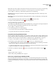
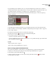
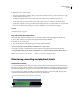
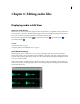
Table Of Contents
- Contents
- Chapter 1: Getting started
- Chapter 2: Digital audio fundamentals
- Chapter 3: Workflow and workspace
- Chapter 4: Setting up Adobe Audition
- Chapter 5: Importing, recording, and playing audio
- Chapter 6: Editing audio files
- Displaying audio in Edit View
- Selecting audio
- Copying, cutting, pasting, and deleting audio
- Visually fading and changing amplitude
- Working with markers
- Creating and deleting silence
- Inverting and reversing audio
- Generating audio
- Analyzing phase, frequency, and amplitude
- Converting sample types
- Recovery and undo
- Chapter 7: Applying effects
- Chapter 8: Effects reference
- Amplitude and compression effects
- Delay and echo effects
- Filter and equalizer effects
- Modulation effects
- Restoration effects
- Reverb effects
- Special effects
- Stereo imagery effects
- Changing stereo imagery
- Binaural Auto-Panner effect (Edit View only)
- Center Channel Extractor effect
- Channel Mixer effect
- Doppler Shifter effect (Edit View only)
- Graphic Panner effect
- Pan/Expand effect (Edit View only)
- Stereo Expander effect
- Stereo Field Rotate VST effect
- Stereo Field Rotate process effect (Edit View only)
- Time and pitch manipulation effects
- Multitrack effects
- Chapter 9: Mixing multitrack sessions
- Chapter 10: Composing with MIDI
- Chapter 11: Loops
- Chapter 12: Working with video
- Chapter 13: Creating surround sound
- Chapter 14: Saving and exporting
- Saving and exporting files
- Audio file formats
- About audio file formats
- 64-bit doubles (RAW) (.dbl)
- 8-bit signed (.sam)
- A/mu-Law Wave (.wav)
- ACM Waveform (.wav)
- Amiga IFF-8SVX (.iff, .svx)
- Apple AIFF (.aif, .snd)
- ASCII Text Data (.txt)
- Audition Loop (.cel)
- Creative Sound Blaster (.voc)
- Dialogic ADPCM (.vox)
- DiamondWare Digitized (.dwd)
- DVI/IMA ADPCM (.wav)
- Microsoft ADPCM (.wav)
- mp3PRO (.mp3)
- NeXT/Sun (.au, .snd)
- Ogg Vorbis (.ogg)
- SampleVision (.smp)
- Spectral Bitmap Image (.bmp)
- Windows Media Audio (.wma)
- Windows PCM (.wav, .bwf)
- PCM Raw Data (.pcm, .raw)
- Video file formats
- Adding file information
- Chapter 15: Automating tasks
- Chapter 16: Building audio CDs
- Chapter 17: Keyboard shortcuts
- Chapter 18: Digital audio glossary
- Index

ADOBE AUDITION 3.0
User Guide
63
The meters show signal levels in dBFS (decibels below full scale), where a level of 0 dB is the maximum amplitude
possiblebeforeclippingoccurs.Yellowpeakindicatorsremainfor1.5secondssothatyoucaneasilydeterminepeak
amplitude.
If amplitude is too low, sound quality is reduced; if amplitude is too high, clipping occurs and produces distortion.
The red clip-indicator to the right of the meters lights up when levels exceed the maximum of 0 dB.
To clear clip indicators, either click them individually or choose Options > Metering > Reset All Indicators.
Monitor levels
Monitoring options differ in Multitrack View and Edit View. In both views, however, you can access these options
from either the Options > Metering menu or the context menu that appears when you right-click meters.
Monitor levels in Multitrack View
Choose any of the following metering options:
Monitor Input Level Monitors audio inputs.
Meter Inputs Only Restricts monitoring to inputs. (By default, multitrack meters show both input and output levels.)
Show All Meters Displays input and output meters for all audio ports in the Levels panel. This option lets you quickly
evaluate all levels in one place.
If your system has a large number of audio ports, you may need to resize the Levels panel to reveal meters for all of
them.
Monitor levels in Edit View
Choose any of the following metering options:
Monitor Record Level Monitors audio inputs. (To quickly enable or disable this option, double-click the meters.)
Show Levels On Play And Record Enables the meters. (Disabling them improves performance on slower computers.)
Customize level meters
Either choose Options > Metering or right-click the meters. Then select any of the following options:
Range options Change the displayed decibel range.
Show Valleys Shows valley indicators at low-amplitude points.
If valley indicators are close to peak indicators, dynamic range (the difference between the quietest and loudest
sounds) is low. If the indicators are spread far apart, dynamic range is high.
Adjust For DC Compensates for DC offset. (For a definition, see “DC offset” on page 274.) During recording, any
offset is indicated by clip indicators in the meters.
Note: Select Adjust For DC if your sound card records with a DC offset, shifting the center of the waveform above or
below the zero amplitude line. This offset can dramatically shift the amplitude measured by meters, causing them to
display levels inaccurately.
Dynamic or Static Peaks Change the mode of peak indicators. Dynamic Peaks resets the yellow peak level indicators
to a new peak level after 1.5 seconds, letting you easily see recent peak amplitude. As the audio gets quieter, the peak
indicators recede. Static Peaks retains peak indicators, letting you determine the maximum amplitude of the signal