
Manual

August 2017August 2017
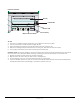
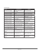
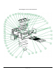
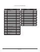
Parts List for the Gas Salamander
Drawing
Number
Description Quantity
1 Top cover plate 1
2 Top cotton pressure plate 1
3 Chamber top plate 1
4 Right sliding sleeve cover plate 1
5 Right sliding assembly 1
6 Lifting assembly 1
7 Screw 2
8 Rack 1
9 Rack supporting assembly 1
10 Shaft pin 2
11 Shaft plate 4
12 Right arm assembly 1
13 Testing plug screw 1
14 NG/LPG Adjusting Valve 3
15 Zinc-alloy knob 3
16 Gas valve 3
17 Gas inlet pipe 1
18 Bottom plate 1
19 1/2 elbow 1
20 1/2 copper connector 1
21 Left strengthen plate 2
22 Rubber foot 4
23 Left sliding sleeve cover plate 1
24 Connecting shaft 1
25 Left/Right side sealing plate 2
26 Left arm assembly 1
27 Left sliding assembly 1
28 Probe supporting plate 1
29 Front beam 1
Drawing
Number
Description Quantity
30 Oil tray 1
31 Rear sealing plate 1
32 Left side plate 1
33 Pipe connecting screw 3
34 Nozzle holder 3
35 Flat nut 3
36 Nozzle 6
37 Rear beam 1
38 Right strengthen plate 2
39 Burner assembly 3
40 Baffl e plate 1
41 Pilot Bracket 3
42 Right Side Plate 1
43 Fixed Plate 3
44 Pilot 3
45 Front panel 1
46 Gear plate 1
47 Cotton Insulation Plate 1