
User`s manual


Getting Started • 31
3
Getting Started
This chapter gives a summary of what is required to setup an operating
system using the PXD-3710/3710F. Hardware installation and BIOS
overview are also discussed. Note that the PXD-3710/3710F is shipped with
CPU, RAM and HDD preinstalled. The installations of the CPU, RAM, and
HDD are done in an ADLINK factory and the procedures described in the
following sections are for users’ reference. If the default configuration does
not fit in your application needs, contact a local ADLINK dealer for special
configurations or OEM.
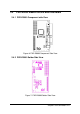
3.1 CPU Installation
The PXD-3710/3710F CPU module supports an Intel Socket 370 FC-PGA
Pentium-III, Celeron, or VIA C3 CPU with a front side bus (FSB) of 100/133
MHz. ADLINK provides efficient CPU fan/cooler to guarantee system
stability.
The Socket 370 uses a standard FC-PGA socket connector. To install the
CPU, insert it to the socket by aligning the notch of the Socket 370 CPU with
the notch of the FC-PGA socket.
Note: Ensure that the CPU heat sink and the CPU top surface are in tight
contact to avoid CPU overheating problems that can cause systems to
hang or crash. The CPU heat sink and fan should be installed tightly
together.
3.2 Memory Installation
ADLINK factory installs a standard 128MB SDRAM in the PXD-3710/3710F.
There are two 144-pin SO-DIMM sockets: DM1 and DM2. The DM1 socket is
on the right-hand side of the PXD-3710/3710F. You have to disassemble the
PXD-3710/3710F to install SDRAM in the DM1 or DM2 socket between the