
User`s manual

Hardware Information 9
PXI-3920/3910
User’s Manual
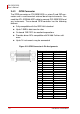
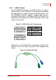
2.4.2 DVI-I Connector
The DVI-I connector is used to connect PXI-3920/3910 to the
monitor. PXI-3920/3910 supports both digital (DVI) and analog
(VGA) monitors. While connecting to an analog (VGA) monitor,
you need to install the DVI-to-VGA adapter, which is shipped with
PXI-3920/3910 controllers, on the DVI-I connector.
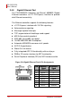
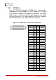
Figure 2-4: DVI Connector & Pin
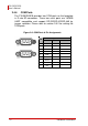
PIN Signal Description
1 TMDS Data2-
2 TMDS Data2+
T.M.D.S link#0 Channel#2 Differential Pair
3 Shield Ground T.M.D.S channel#0 Shield
4 Reserved Reserved for link#1
5 Reserved Reserved for link#1
6 DDC Clock The clock line for the DDC I/F
7 DDC Data The data line for the DDC I/F
8 Analog VSYNC Vertical synchronization signal for the analog interface
9 TMDS Data1-
10 TMDS Data1+
T.M.D.S link#0 Channel#1 Differential Pair
11 Shield Ground T.M.D.S channel#1 Shield
12 Reserved Reserved for link#1
13 Reserved Reserved for link#1
14 +5V Power Provide by the system to enable the monitor to provide EDID
15 Ground Return for +5V,HSync and VSync
16 Hot Plug Detect Driven by monitor to enable the system to identify the presence of a monitor
17 TMDS Data0-
18 TMDS Data0+
T.M.D.S link#0 Channel#0 Differential Pair
19 Shield Ground T.M.D.S channel#0 Shield
20 Reserved Reserved for link#1
21 Reserved Reserved for link#1
22 Ground T.M.D.S Clock Shield
23 TMDS Clock+
24 TMDS Clock-
T.M.D.S Clock Differential Pair
C1 Analog Red Analog Red Signal
C2 Analog Green Analog Green Signal
C3 Analog Blue Analog Blue Signal
C4 Analog HSYNC Vertical synchronization signal for the analog input
C5 Analog Ground Analog R,G and B return
Assignments