
User`s manual


Backplane Overview 25
asynchronous external events the system is monitoring or control-
ling.
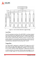
System Reference Clock
The PXIS-2680P supplies the PXI 10MHz system clock signal
(PXI_CLK10) independently to every peripheral slot. An indepen-
dent buffer (having a source impedance matched to the backplane
and a skew of less than 1ns between slots) drives the clock signal
to each peripheral slot. Users can use this common reference
clock signal to synchronize multiple modules in a measurement or
control system or drive PXI_CLK10 from an external source
through the PXI_CLK10_IN pin on the P2 connector of the star
trigger slot. Users can select the internal or external clock by set-
ting the jumper JP2 and JP3 in the back of the backplane.
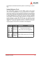
JP2 JP3 Pin 1-2 Description
Open JP2
Short JP3
External clock through the
PXI_CLK10_IN on star trigger slot
Short JP2
Open JP3
(default)
Internal 10MHz system clock PXI_CLK10
Table 3-1: JP2 and JP3 PXI Reference Clock Control